Brushless servo motor tester

a servo motor and tester technology, applied in the direction of motor/generator/converter stopper, dynamo-electric converter control, instruments, etc., can solve the problems of costly downtime, difficult diagnosis of feedback system, suspicion often falling on the motor, etc., to simplify the determination of motor configuration and operating parameters.

Inactive Publication Date: 2008-12-09
MITCHELL ELECTRONICS
View PDF15 Cites 22 Cited by
  • Summary
  • Abstract
  • Description
  • Claims
  • Application Information

AI Technical Summary

Problems solved by technology

Applications are often complex, three-dimensional positioning along with rotary alignment requiring multiple axes of control, operating cooperatively, to accomplish a task.
Feedback systems are often difficult to diagnose and systems with multiple feedback loops, such as motion control system 90, compound the problem.
Because the system is not moving, suspicion often falls on motor 10, which is then removed and replaced.
Because these motors are often embedded in complex machine tools, costly downtime ensues and oftentimes the problem remains after motor replacement.
Motors are often not directly labeled with enough information to directly determine the operating parameters and configuration.
The step of identifying the operating parameters and configuration from the motor part number is time consuming and error prone.
The prior art does not sufficiently address in situ servo motor testing.

Method used


Image

  • Brushless servo motor tester
  • Brushless servo motor tester
  • Brushless servo motor tester

Examples


Embodiment Construction

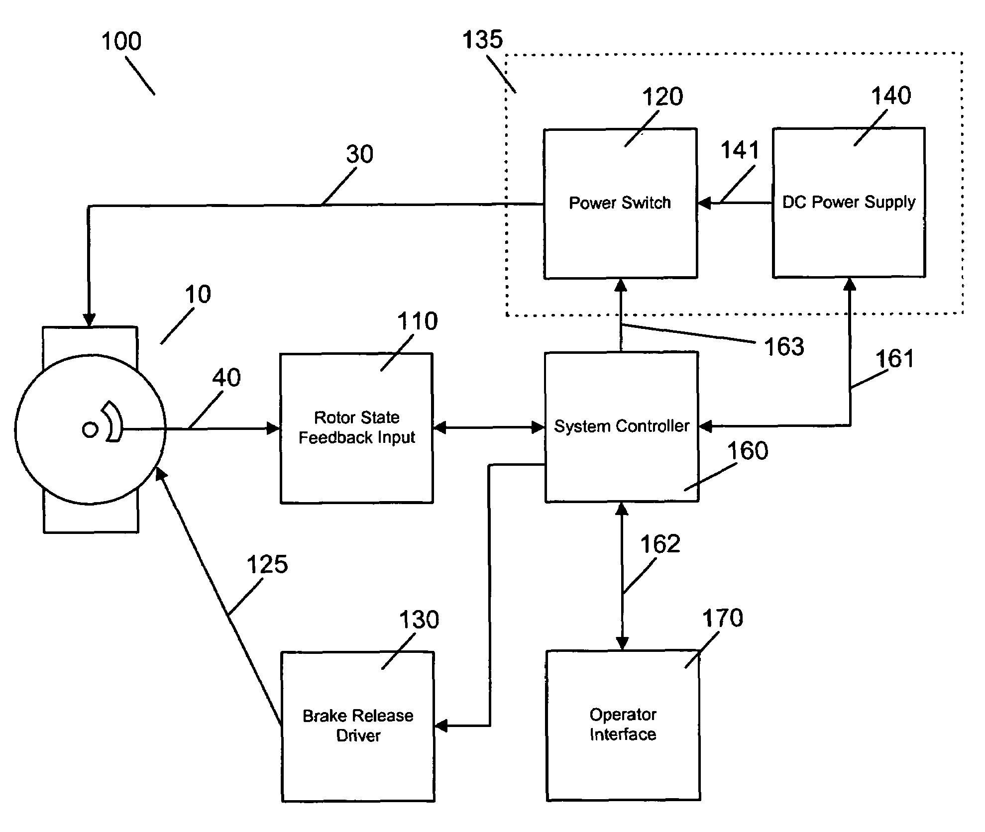
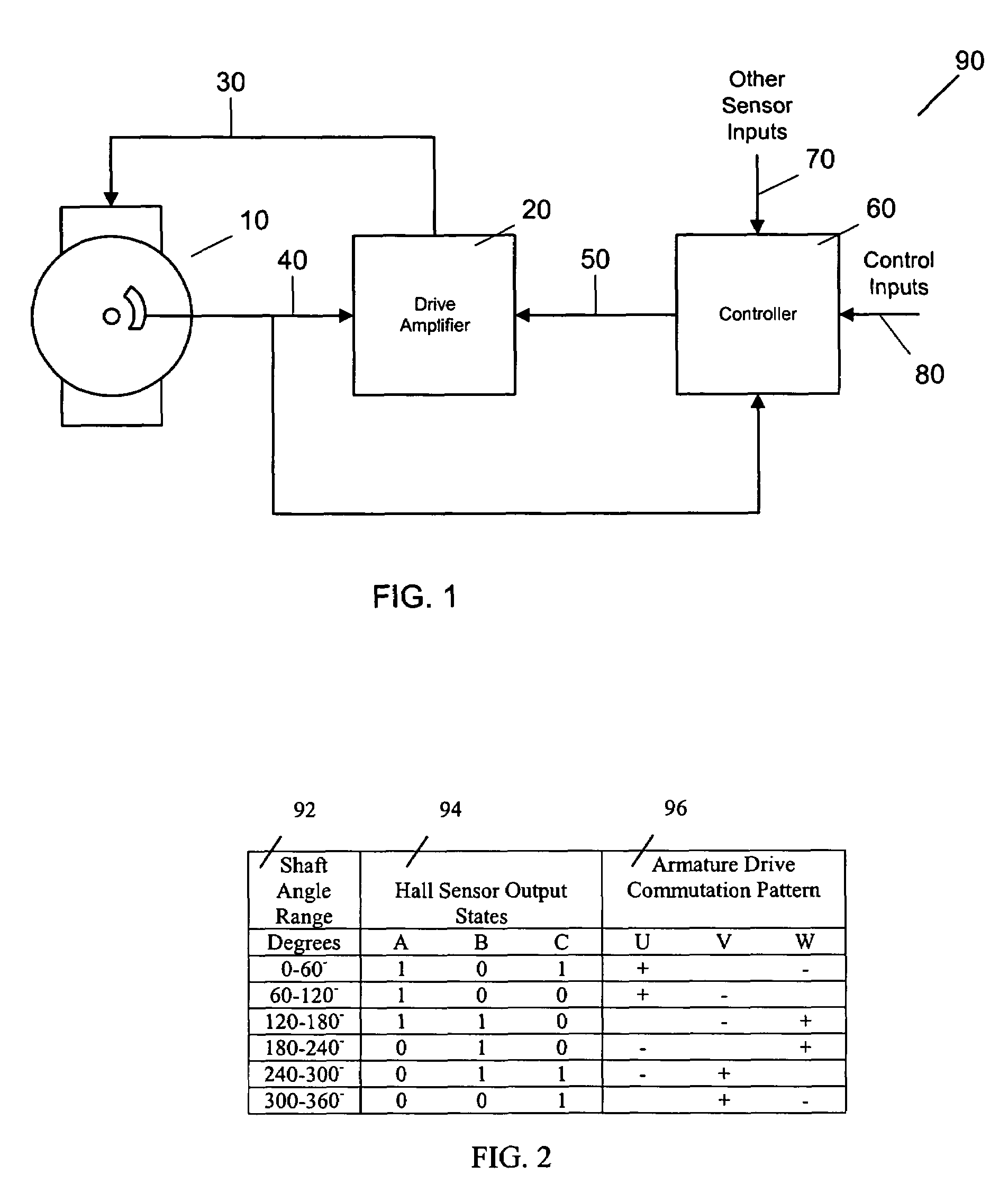
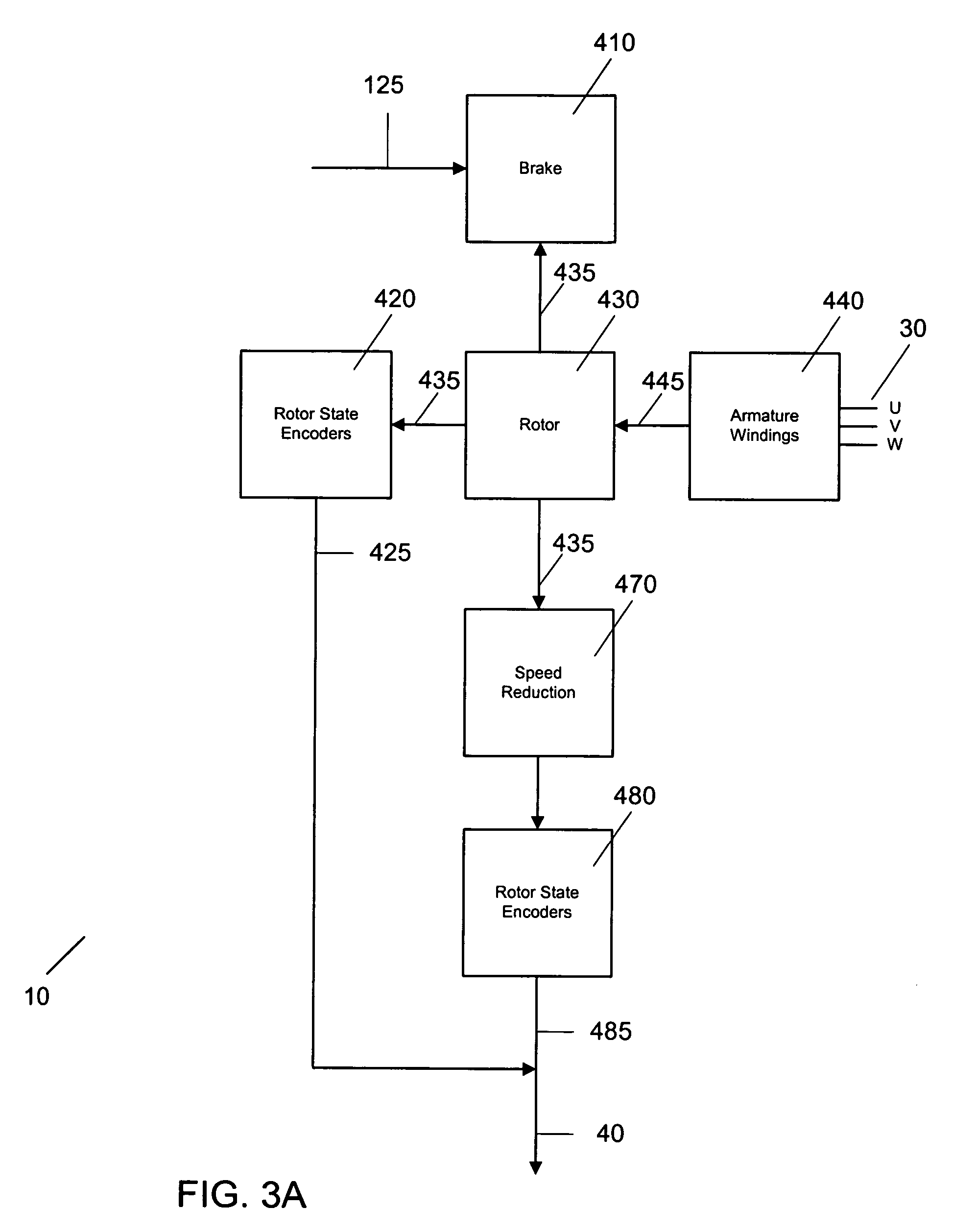
[0034]Referring to FIG. 3A, a permanent magnet brushless (PMBL) servo motor block diagram is shown at 10. The PMBL motor comprises a rotor 430, a motor shaft 435, armature 440, and rotor state encoders 420 producing direct rotor state feedback 425. A PMBL motor may additionally comprise a brake 410 with an electric release input 125, the brake generally used to hold the motor shaft when the motor is unpowered. Motor 10 may drive another rotating machine, possibly through speed reduction 470, the rotating machine being equipped with rotor state encoders 480 producing indirect rotor state feedback 485. Direct rotor state feedback 425 and indirect rotor state feedback 485 combine to provide rotor state feedback 40. A case (not shown) provides mechanical support for the motor components. When motor 10 is connected to drive amplifier 20 and controller 60 as shown in FIG. 1, motor 10 is part of a control axis that performs a motive task.

[0035]At the core of PMBL motor 10 is moveable rotor...


PUM


Abstract

A permanent magnet brushless (PMBL) servo motor test apparatus and method allow testing of a motor in place. A set of static and dynamic tests is performed to determine proper motor operation of armature windings and rotor feedback devices. The test system of the present invention displaces the motor drive system. The test system comprises an armature driver, a feedback device input, and a system controller. The armature windings of the motor-under-test are driven in a polarity sequence according to a test sequence, whereby the rotor is driven in a series of rotations. Angle feedback is tested at a plurality of said rotations. Rotor velocity outputs are tested during said rotations. Armature current and voltage are determined at a plurality of said rotations and winding balance is tested. Said power switch is also operative to apply a voltage between the armature windings and the motor case to test for fault current flow.In another embodiment of the invention, motor identification is decoded by the system into motor configuration and motor operation parameters, necessary to test the motor. Motor identification may be entered by an operator or captured from machine readable tags such as a barcode tag or an RFID tag.

Description

BACKGROUND[0001]1. Field of Invention[0002]This invention relates generally to a brushless servo motor tester and specifically to a brushless servo motor tester that tests a motor in its operating environment.[0003]2. Description of Prior Art[0004]Industrial automation applications often use permanent magnet brushless (PMBL) servo motors for positioning. Applications are often complex, three-dimensional positioning along with rotary alignment requiring multiple axes of control, operating cooperatively, to accomplish a task.[0005]A typical PMBL servo motor comprises an armature with armature windings, a rotor, and rotor state feedback. The rotor is connected to, and is rotatably supported by, a motor shaft, on an axis of rotation. The rotor angle is a mechanical angle representing shaft rotation. The rotor comprises one or more permanent magnet pole pairs. The armature windings, when powered, produce an armature magnetic field that interacts with the rotor field to produce rotor torq...

Claims


Application Information

Patent Timeline
Patent Type & Authority Patents(United States)
IPC IPC(8): G01R31/34
CPCG01R31/343
Inventor MITCHELL, LAWRENCE HARDYMITCHELL, STUART GLEN
Owner MITCHELL ELECTRONICS
Why Eureka
Try Eureka