Electret condenser microphone

a condenser microphone and condenser technology, applied in the field of electret condenser microphones, can solve problems such as difficulty in miniaturization, achieve the effects of enhancing the high-frequency characteristic of electret condensers, reducing parasitic capacitance and noise, and reducing the volume of the back air chamber of electret condensers

Active Publication Date: 2008-12-16
TDK CORPARATION
View PDF16 Cites 65 Cited by
  • Summary
  • Abstract
  • Description
  • Claims
  • Application Information

AI Technical Summary

Benefits of technology

[0012]In the present invention, electric contact between the substrate and the electret condenser is established at a mechanical contact part therebetween, in other words, the substrate and the electret condenser are connected to each other electrically without using a wire bonder, suppressing parasitic capacitance and noise occurrence caused due to the presence of the bonding wire. This enhances the high-frequency characteristic of the electret condenser. Further, the substantial volume of the back air chamber of the electret condenser can be increased by utilizing the space (the internal region of the case) formed by the case that covers the electret condenser, so that the high-frequency characteristic of the condenser can be enhanced even when the electret condenser is miniaturized.
[0013]As described above, according to the present invention, a small-size electret condenser microphone excellent in high-frequency characteristic can be provided.

Problems solved by technology

However, an ECM of the type disclosed in Patent Document 1, which uses mechanically-processed components, encounters difficulty in miniaturization.

Method used


Image

  • Electret condenser microphone
  • Electret condenser microphone
  • Electret condenser microphone

Examples


Embodiment Construction

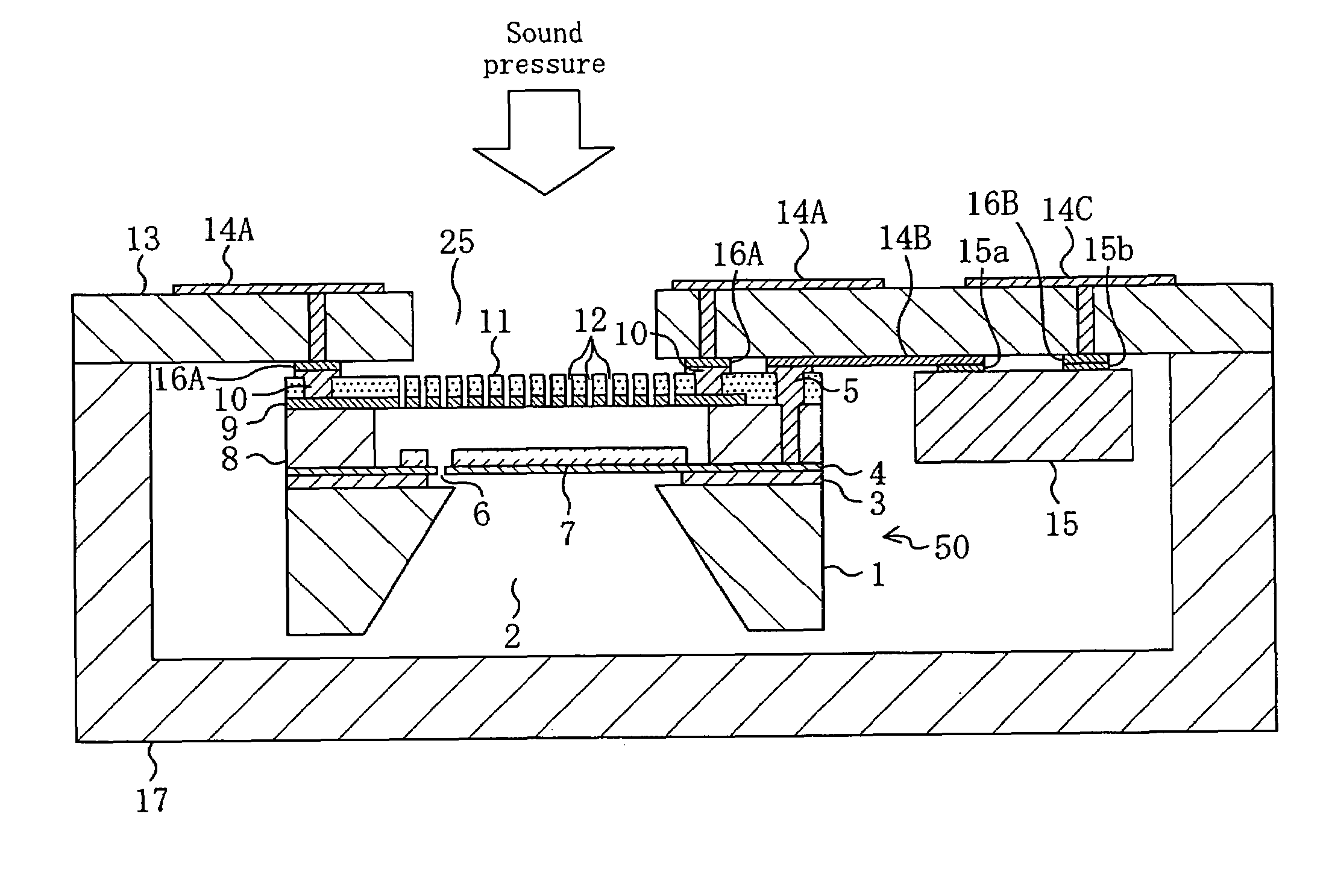
[0042]An electret condenser microphone according to one embodiment of the present invention will be described below with reference to the accompanying drawings.

[0043]Fist of all, a description will be given to an electret condenser (hereinafter referred to as an electret condenser of the present invention) carried by an electret condenser microphone according to the present embodiment. The electret condenser of the present invention is manufactured by a processing method called surface micro machining in the MEMS technology which uses only a single silicon substrate.

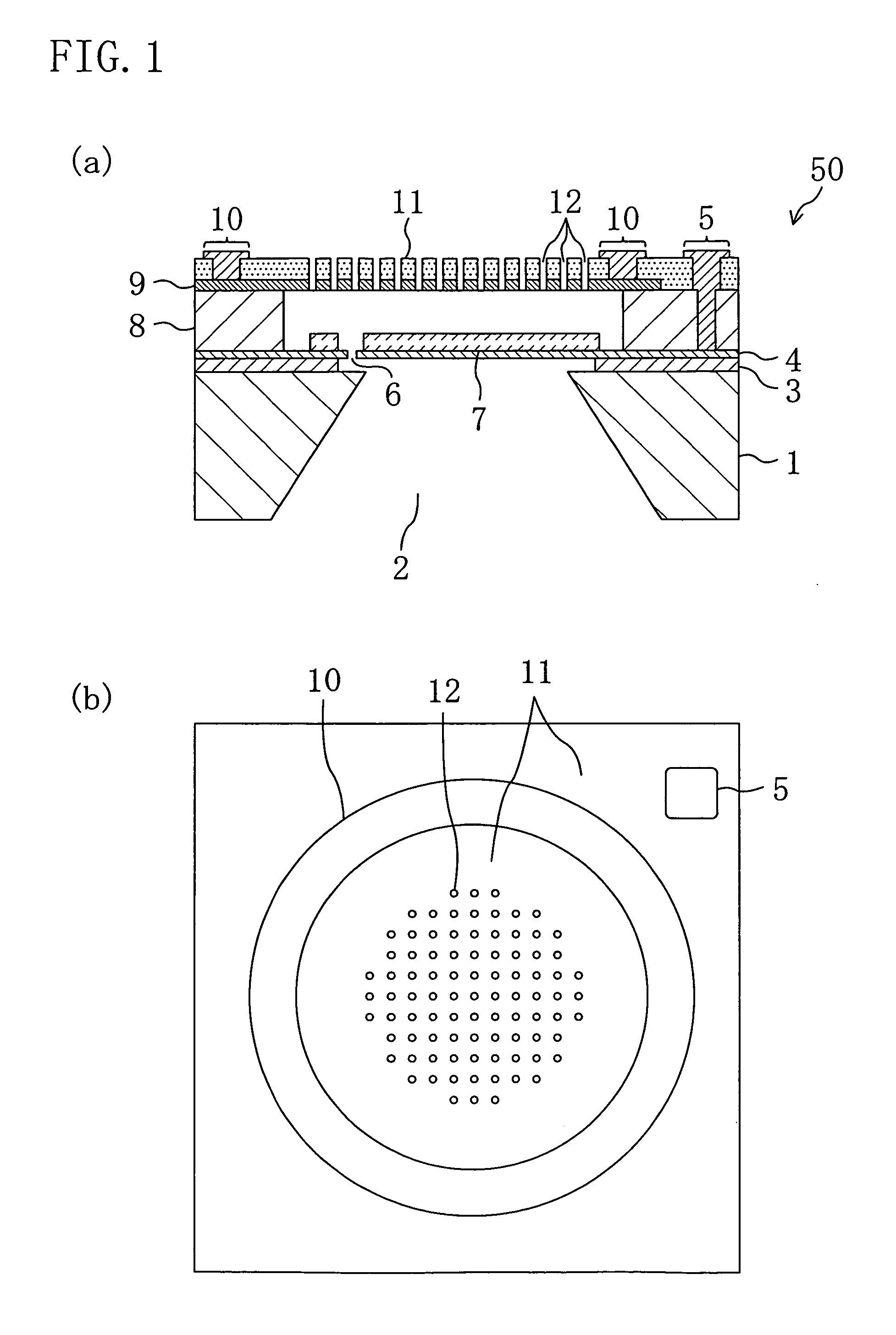
[0044]FIG. 1(a) and FIG. 1(b) are a sectional view and a plan view of an electret condenser 50 of the present invention, respectively.

[0045]As shown in FIG. 1(a) and FIG. 1(b), a cavity 2 is formed in a silicon substrate 1 by anisotropic etching, and an insulating film 3 formed of, for example, a silicon oxide film and a lower electrode 4 formed of, for example, a polysilicon film doped with phosphorus are formed on the ...


PUM


Abstract

An electret condenser microphone includes: a substrate 13 in which an opening 25 is formed; an electret condenser 50 connected to one face of the substrate 13 so as to close the opening 25 and having an acoustic hole 12 and a cavity 2; a drive circuit element 15 connected to the one face of the substrate 13; and a case 17 mounted over the substrate 13 so as to cover the electret condenser 50 and the drive circuit element 15. Electric contact is established at a joint part between the electret condenser 50 and the substrate 13. The acoustic hole 12 communicates with an external space through the opening 25. The cavity 2 and an internal region of the case 17 serve as a back air chamber for the electret condenser 50.

Description

RELATED APPLICATION[0001]This application is a national phase of PCT / JP2005 / 003031 filed on Feb. 24, 2005, which claims priority from Japanese Application No. 2004-065190 filed Mar. 9, 2004, the disclosures of which Applications are incorporated by reference herein. The benefit of the filing and priority dates of the International and Japanese Applications is respectfully requested.TECHNICAL FIELD[0002]The present invention relates to an electret condenser microphone including a vibrating electrode, and particularly relates to a structure of an electret condenser microphone (ECM) carrying an electret condenser formed using a MEMS (Micro Electro Mechanical System) technology.BACKGROUND ART[0003]Conventionally, predominant condenser microphones are microphones in which components, such as a diaphragm, a fixed electrode, and the like separately manufactured by a mechanical processing or the like are incorporated, as disclosed in Patent Document 1. These microphones are called ECMs (Ele...

Claims


Application Information

Patent Timeline
Patent Type & Authority Patents(United States)
IPC IPC(8): H04R25/00H04R19/00H04R19/01
CPCB81B7/0061H04R19/016H04R19/005B81B2201/0257B81B2207/012B81B2203/0127H01G7/02H04R19/04H04R19/01
Inventor OGURA, HIROSHIYAMAOKA, TOHRU
Owner TDK CORPARATION
Why Eureka
Try Eureka