Liquid crystal display apparatus, drive circuit therefor, and drive method therefor

a technology of liquid crystal display and drive circuit, which is applied in the direction of electric digital data processing, instruments, computing, etc., can solve the problems of deterioration of liquid crystal properties, and achieve the effects of suppressing sound emission, increasing current consumption, and suppressing charging and discharging of liquid crystal capacitance during the second period

Inactive Publication Date: 2012-03-15
SHARP KK
View PDF2 Cites 5 Cited by
  • Summary
  • Abstract
  • Description
  • Claims
  • Application Information

AI Technical Summary

Benefits of technology

[0073]According to the first aspect of the present invention, by alternately providing a high-level potential and a low-level potential to the common electrode during the second period of each horizontal scanning period, the drive frequency of the common electrode can be brought out of the human-audible frequency band. In addition, two or more potentials are prepared as the high-level side potential of the common electrode and two or more potentials are prepared as the low-level side potential of the common electrode. A high-level side potential provided to the common electrode during the second period of each horizontal scanning period is set to a level lower than that of a high-level side potential provided to the common electrode during the first period of the horizontal scanning period. In addition, a low-level side potential provided to the common electrode during the second period of each horizontal scanning period is set to a level higher than that of a low-level side potential provided to the common electrode during the first period of the horizontal scanning period. Namely, the amplitude of a signal for driving the common electrode (common electrode signal) is smaller for the second period than for the first period. Hence, an increase in current consumption caused by charging and discharging of a liquid crystal capacitance during the second period is suppressed. By the above, a liquid crystal display apparatus is implemented that is capable of suppressing sound emission caused by alternating driving of liquid crystal while suppressing an increase in power consumption.
[0074]According to the second aspect of the present invention, the frequency of a second period potential instruction signal indicating whether a potential to be provided to the common electrode during the second period of a horizontal scanning period is a low-level side potential or a high-level side potential can be changed externally. Hence, by externally adjusting the frequency of the second period potential instruction signal, the frequency of the common electrode signal for the second period can be set to a desired frequency. Accordingly, the frequency of the common electrode signal for the second period can be set according to the drive conditions of the common electrode which vary from device to device, enabling to suppress sound emission in various devices which is caused by alternating driving of liquid crystal. In addition, by minimizing the frequency of the common electrode signal for the second period within a range in which sound emission does not occur, an increase in power consumption is suppressed.
[0075]According to the third aspect of the present invention, the high-level side potential and low-level side potential of the common electrode for the second period of a horizontal scanning period can be set externally. Hence, the amplitude of the common electrode signal for the second period of a horizontal scanning period can be set to a desired magnitude. Accordingly, the amplitude of the common electrode signal can be minimized within a range in which sound emission does not occur, enabling to suppress sound emission caused by alternating driving of liquid crystal while effectively suppressing an increase in power consumption.
[0076]According to the fourth aspect of the present invention, the frequency and amplitude of the common electrode signal for the second period of a horizontal scanning period can be set according to the device. Hence, sound emission caused by alternating driving of liquid crystal can be suppressed while an increase in power consumption is more effectively suppressed.
[0077]According to the fifth aspect of the present invention, in a liquid crystal display apparatus including a common electrode drive circuit including: a low-level side potential selecting unit that selects a low-level side potential to be provided to the common electrode; a high-level side potential selecting unit that selects a high-level side potential to be provided to the common electrode; a potential providing unit that provides the potential selected by the low-level side potential selecting unit or the high-level side potential selecting unit to the common electrode; and a potential selection signal providing unit that provides a potential selection signal indicating whether a potential to be provided to the common electrode is a low-level side potential or a high-level side potential, to the potential providing unit, the same effects as those obtained by the first aspect of the present invention are obtained.
[0078]According to the sixth aspect of the present invention, in a liquid crystal display apparatus including a common electrode drive circuit including a low-level side potential selecting unit, a high-level side potential selecting unit, a potential providing unit, and a potential selection signal providing unit, the same effects as those obtained by the second aspect of the present invention are obtained.

Problems solved by technology

Meanwhile, liquid crystal has the property of deteriorating with continuous application of a direct voltage thereto.

Method used


Image

  • Liquid crystal display apparatus, drive circuit therefor, and drive method therefor
  • Liquid crystal display apparatus, drive circuit therefor, and drive method therefor
  • Liquid crystal display apparatus, drive circuit therefor, and drive method therefor

Examples


first embodiment

1. First Embodiment

[0097]

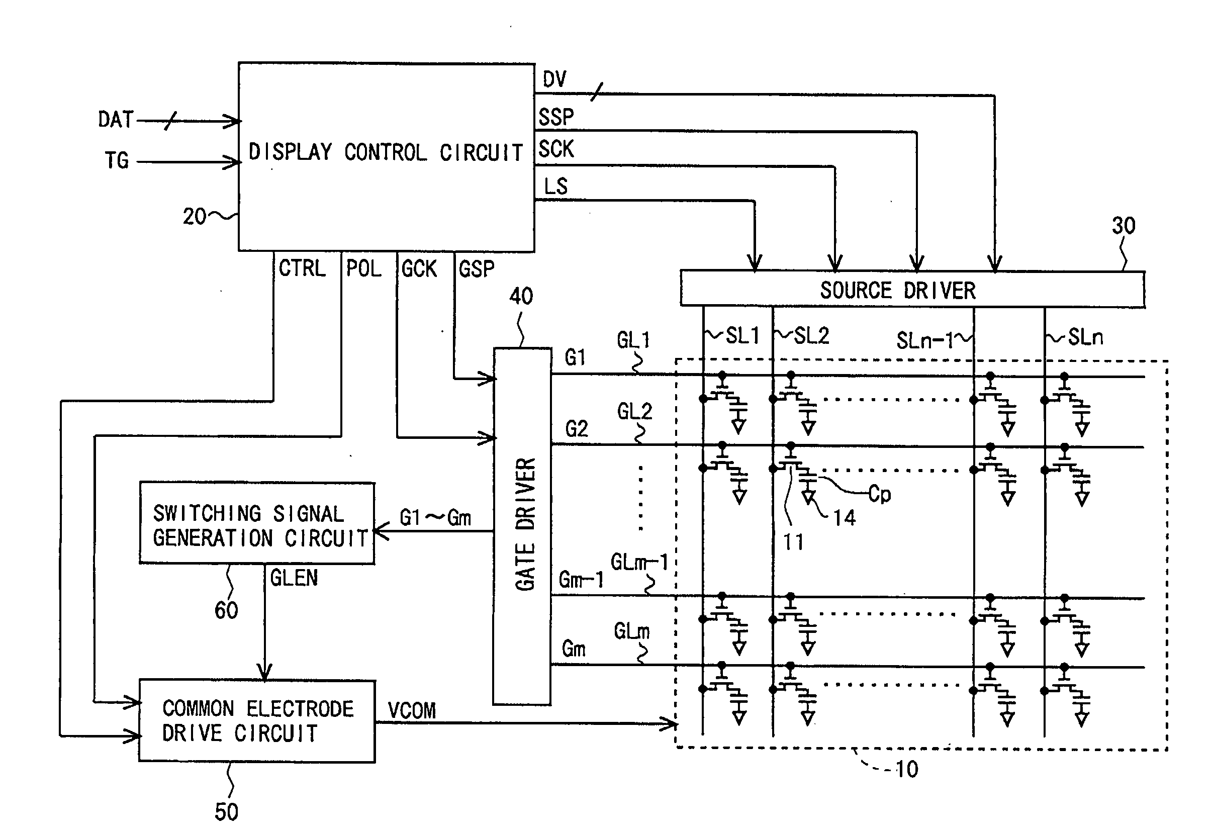
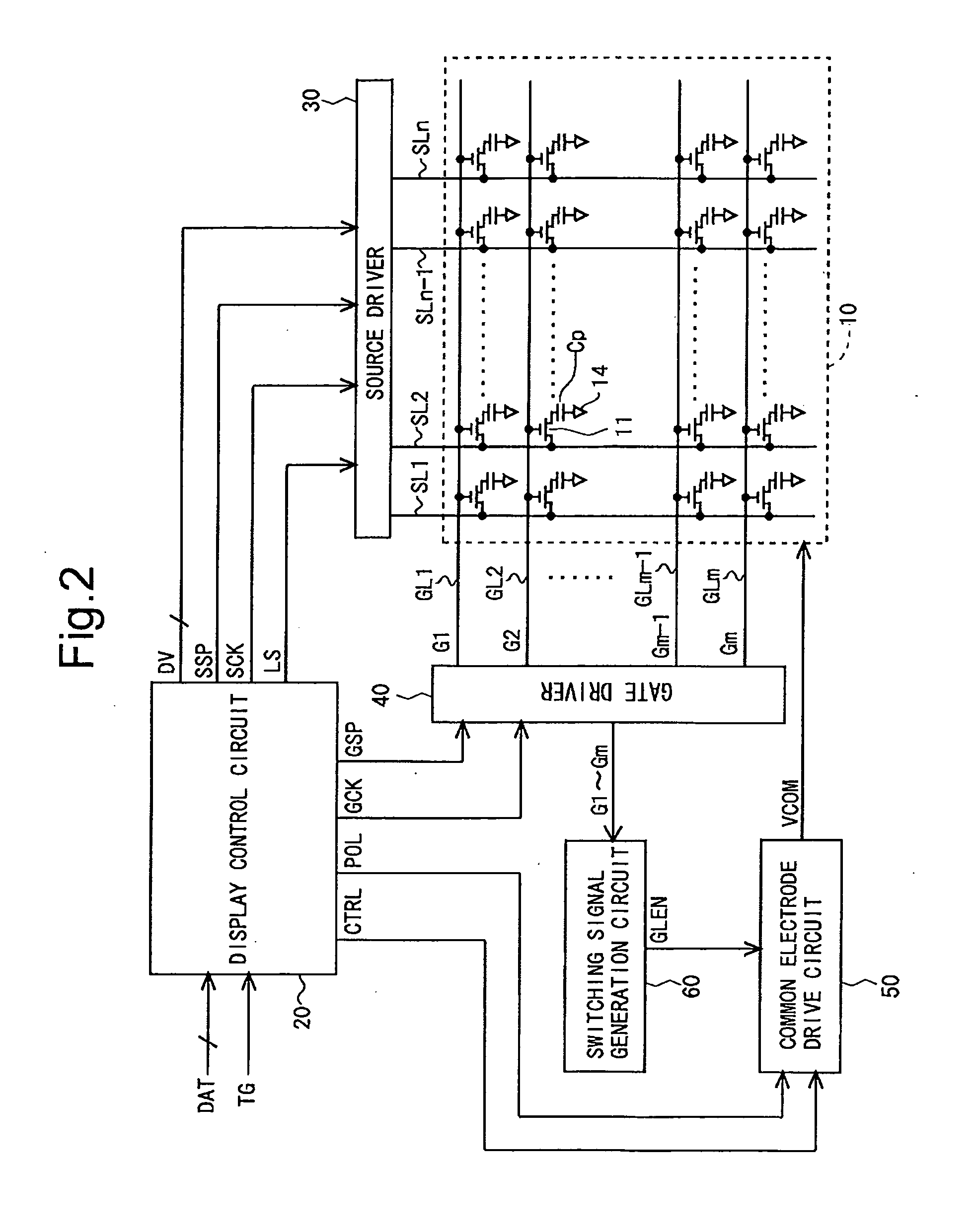
[0098]FIG. 2 is a block diagram showing an overall configuration of a liquid crystal display apparatus according to a first embodiment of the present invention. The liquid crystal display apparatus includes a display unit 10, a display control circuit 20, a source driver (video signal line drive circuit) 30, a gate driver (scanning signal line drive circuit) 40, a common electrode drive circuit 50, and a switching signal generation circuit 60.

[0099]The display unit 10 includes a plurality of (n) source bus lines (video signal lines) SL1 to SLn, a plurality of (m) gate bus lines (scanning signal lines) GL1 to GLm, and a plurality of (n×m) pixel formation portions provided at the respective intersections of the plurality of source bus lines SL1 to SLn and the plurality of gate bus lines GL1 to GLm. The pixel formation portions are arranged in a matrix form, thereby forming a pixel array. Each pixel formation portion is composed of a TFT 11 which is a switching...

second embodiment

2. Second Embodiment

[0122]

[0123]FIG. 6 is a circuit diagram showing a configuration of a common electrode drive circuit 50 of a second embodiment of the present invention. In the present embodiment, the configuration is such that a frequency control circuit 550 is provided so that the frequency of a reversal timing control signal CTRL can be controlled (changed) externally, and a reversal timing control signal CTRL outputted from the frequency control circuit 550 is provided to an input terminal of an AND circuit 532. Other configurations are the same as those in the above-described first embodiment and thus description thereof is omitted. Note that the frequency control circuit 550 may be provided inside the common electrode drive circuit 50 or may be provided outside the common electrode drive circuit 50.

[0124]

[0125]FIGS. 7A to 7F are timing charts for describing a method of driving a common electrode 14 in the present embodiment. As with the first embodiment, in the present embod...

third embodiment

3. Third Embodiment

[0129]

[0130]FIG. 8 is a circuit diagram showing a configuration of a common electrode drive circuit 50 of a third embodiment of the present invention. In the present embodiment, there are provided a fourth potential selecting unit 564 for selecting a potential LV4 generated by a fourth power supply 514 from among arbitrary levels in a predetermined range; and a third potential selecting unit 563 for selecting a potential LV3 generated by a third power supply 513 from among arbitrary levels in a predetermined range. The fourth potential selecting unit 564 includes a register which can be set externally. The fourth potential selecting unit 564 makes a selection of the level of the potential LV4 based on data (second setting information) stored in the register. Likewise, the third potential selecting unit 563 also includes a register which can be set externally. The third potential selecting unit 563 makes a selection of the level of the potential LV3 based on data (...


PUM


Abstract

A liquid crystal display apparatus is disclosed, which is capable of suppressing sound emission caused by the AC drive of liquid crystal while suppressing an increase in power consumption. A non-active period during which polarity reversal of a common electrode signal (VCOM) is repeated at predetermined intervals is provided in each horizontal scanning period. During an active period, a common electrode drive circuit provides a common electrode signal (VCOM) indicating either one of potentials LV1 and LV2 to a common electrode, based on a polarity instruction signal (POL). During the non-active period, the common electrode drive circuit provides a common electrode signal (VCOM) whose potential changes between LV3 and LV4 to the common electrode, based on a reversal timing control signal (CTRL). Here, the amplitude of the common electrode signal (VCOM) for the non-active period is made smaller than the amplitude of the common electrode signal (VCOM) for the active period.

Description

TECHNICAL FIELD[0001]The present invention relates to a liquid crystal display apparatus, and more particularly to a technique for preventing sound emission caused by vibration in a small liquid crystal display apparatus which is adopted in mobile phones, etc.BACKGROUND ART[0002]Conventionally, there is known an active matrix-type liquid crystal display apparatus including TFTs (Thin Film Transistors) as switching elements. This liquid crystal display apparatus includes a liquid crystal panel composed of two insulating glass substrates facing each other. One glass substrate of the liquid crystal panel is provided with gate bus lines (scanning signal lines) and source bus lines (video signal lines) in a grid pattern, and is provided with TFTs near the respective intersections of the gate bus lines and the source bus lines. Each TFT is composed of a gate electrode connected to a gate bus line; a source electrode connected to a source bus line; and a drain electrode. The drain electrod...

Claims


Application Information

Patent Timeline
Patent Type & Authority Applications(United States)
IPC IPC(8): G09G5/00G09G3/36
CPCG09G3/3655G09G2330/021G09G2310/06
Inventor SUYAMA, TATSUHIKOOHMURA, NORIO
Owner SHARP KK
Why Eureka
Try Eureka