Method and apparatus for an elevator system for a multilevel cleanspace fabricator

a fabricator and elevator technology, applied in the direction of chemistry apparatus and processes, instruments, transportation and packaging, etc., can solve the problems of inability additional challenges of standalone implementations, and difficult, if not impossible, to install or remove fabricator tools

Inactive Publication Date: 2008-12-16
FUTRFAB
View PDF75 Cites 53 Cited by
  • Summary
  • Abstract
  • Description
  • Claims
  • Application Information

AI Technical Summary

Benefits of technology

[0006]Accordingly, the present invention provides methods and apparatus for transporting a fabricator tool to or from a cleanspace environment within a work area module defined in three dimensions by walls. The work space module includes a connecting surface connectable to a tool location in a multilevel fabricator. The connecting surface can include a perimeter defining an opening in at least one wall containing the work area, wherein the opening is large enough to allow a fabricator tool to pass through the opening. A support structure can support the work area module and also include automation for transporting the work area module in at least one of a horizontal plane and a vertical plane. Each plane can be relative to the cleanspace environment. A seal can be present between the perimeter defining the opening and a surface of the cleanspace environment. The seal can be operative to preserve the integrity of an atmosphere defined by the cleanspace environment and an environment within the work area module.
[0015]Other embodiments can include methods of facilitating placement of a fabrication tool in a fabricator by elevating a work area module and transporting the work area module in a horizontal plane to a tool location. A connecting surface can seal the work area module to a tool location in the fabricator. The seal can be sufficient to maintain a cleanspace environment about a fabricator tool while the fabricator tool is transported between the work space module and the tool location.

Problems solved by technology

Stand alone implementations pose additional challenges for installing and removing tools.
In particular, it would be difficult, if not impossible to install or remove a fabricator tool while maintaining the tool in a clean space environment.

Method used


Image

  • Method and apparatus for an elevator system for a multilevel cleanspace fabricator
  • Method and apparatus for an elevator system for a multilevel cleanspace fabricator
  • Method and apparatus for an elevator system for a multilevel cleanspace fabricator

Examples


Embodiment Construction

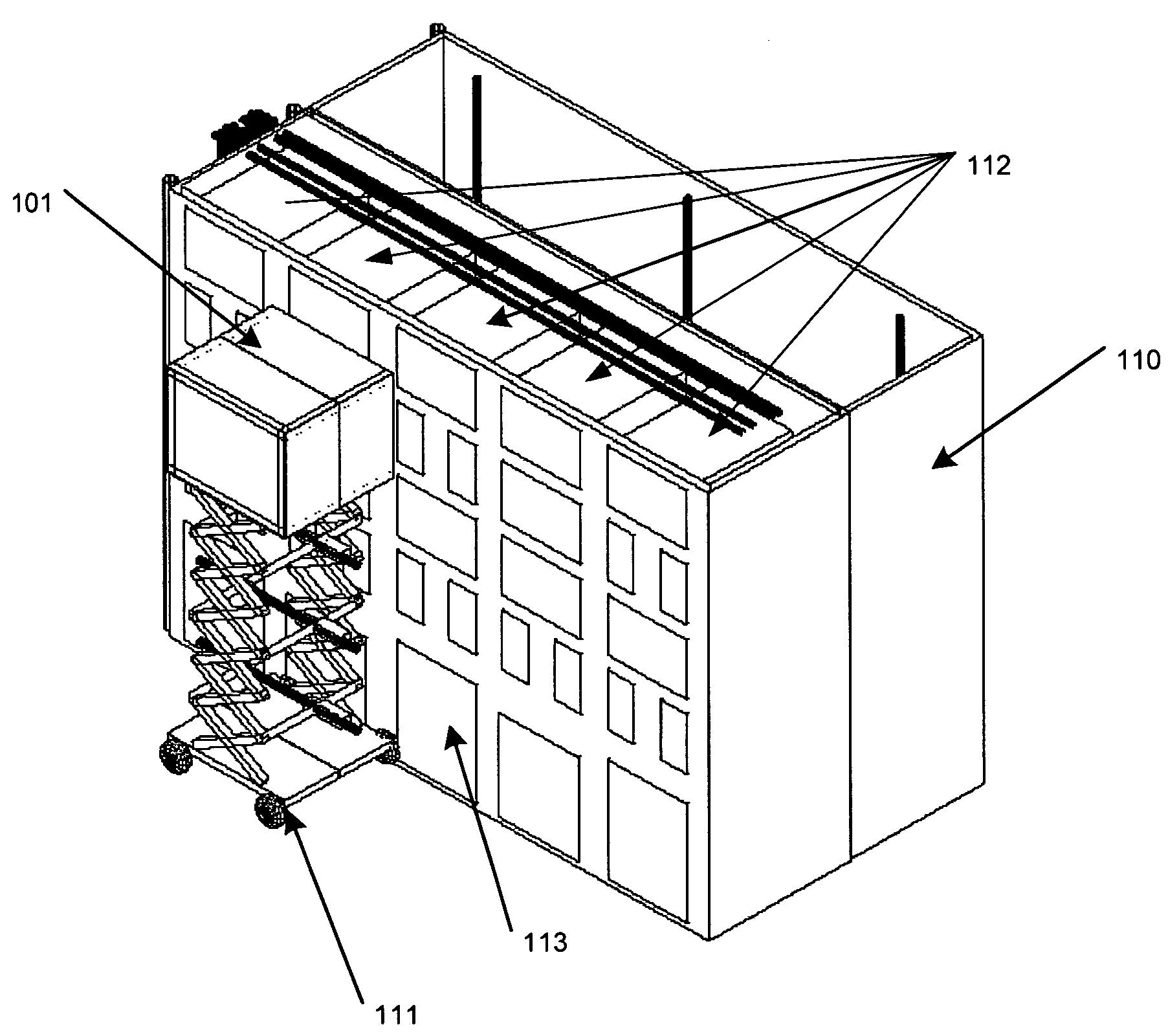
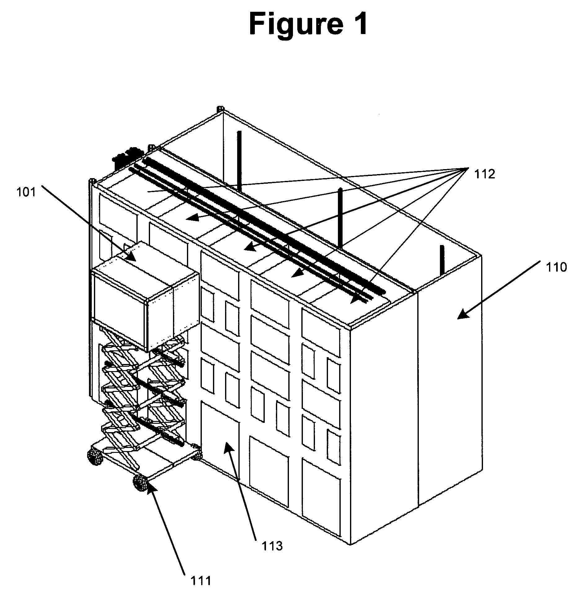
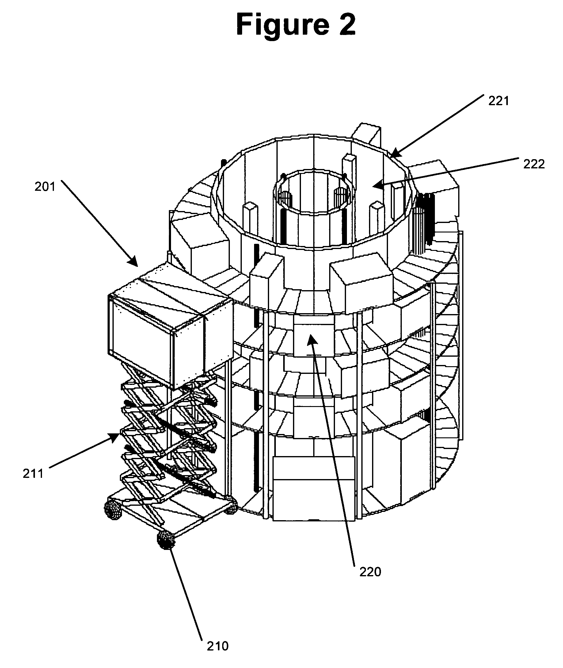
[0027]The present invention relates to methods and apparatus to support a cleanspace environment within which a material, such as an integrated circuit substrate, can be processed. In particular, according to the present invention, the support includes methods and apparatus which allow multiple fabrication tools used to process a material within the cleanspace to be arranged in a vertical and horizontal matrix. In some embodiments of the present invention, a portion of each fabrication tool can be made accessible from within a cleanspace in which the material is processed and an additional portion of each fabrication tool can be positioned within a separate cleanspace environment. A unique elevator is provided for transporting fabrication tools to and from various positions in the matrix and also allow for the fabrication tool to be placed into, or removed from, the matrix while maintaining the integrity of a cleanspace environment around the fabrication tool.

[0028]Reference will no...


PUM


Abstract

The present invention provides methods and apparatus capable of routine placement and replacement of fabricator tools in a designated tool location. The tool location can be selected from multiple tool locations arranged in a matrix with horizontal and vertical designations. In another aspect, the fabricator tool placement and replacement can be accomplished while maintaining a clean space environment about the fabricator tool.

Description

CROSS REFERENCE TO RELATED APPLICATIONS[0001]This application claims priority to the Provisional Application, Ser. No. 60 / 596,343, filed Sep. 18, 2005 and entitled: Specialized Methods for Substrate Processing for a Clean Space Where Processing Tools are Vertically Oriented; and also Provisional Application, Ser. No. 60 / 596,173, filed Sep. 6, 2005 and entitled: “Method and Apparatus for Substrate Handling for a Clean Space where processing tools are reversibly removable”; and also Provisional Application, Ser. No. 60 / 596,099, filed Aug. 31, 2005 and entitled: “Method and Apparatus for a Single Substrate Carrier For Semiconductor Processing; and also Provisional Application, Ser. No. 60 / 596,053 filed Aug. 26, 2005 and entitled: “Method and Apparatus for an Elevator System for Tooling and Personnel for a Multilevel Cleanspace / Fabricator”. The contents of each are relied upon and incorporated by reference.FIELD OF THE INVENTION[0002]The present invention relates to apparatus and method...

Claims


Application Information

Patent Timeline
Patent Type & Authority Patents(United States)
IPC IPC(8): G06F19/00B01L1/04
CPCH01L21/67724H01L21/67736H01L21/67769H01L21/67775
Inventor FLITSCH, FREDERICK A.
Owner FUTRFAB
Why Eureka
Try Eureka