
Asynchronous switch based on butterfly fat-tree for network on chip application

a network on chip and butterfly technology, applied in the field of system on chip soc, can solve problems such as not allowing another data packet, and achieve the effects of simplifying the control logic circuit, maximizing the performance of the switch, and being useful in the large-scale communication network

Inactive Publication Date: 2008-12-16
GWANGJU INST OF SCI & TECH
View PDF5 Cites 62 Cited by
  • Summary
  • Abstract
  • Description
  • Claims
  • Application Information

AI Technical Summary

Benefits of technology

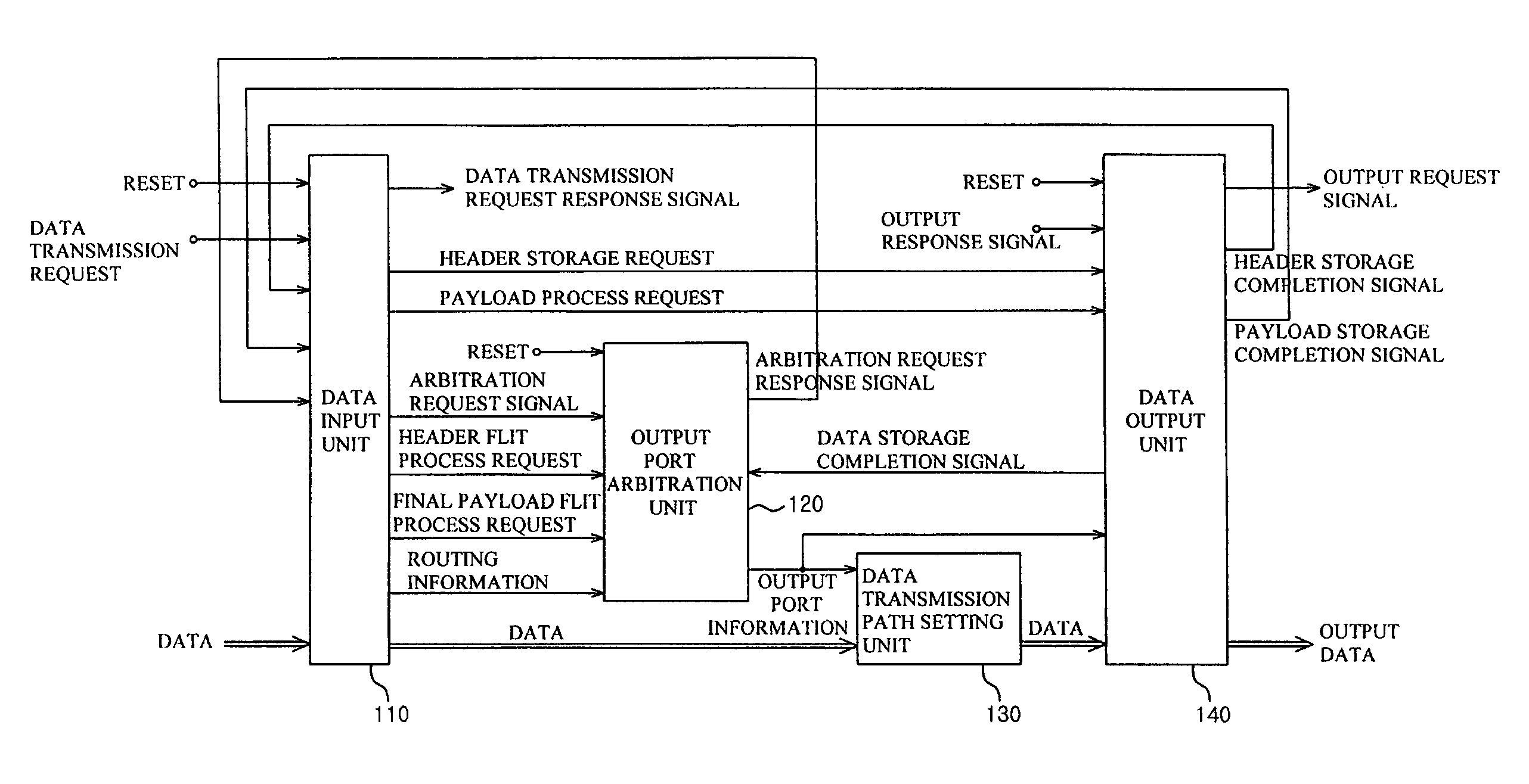
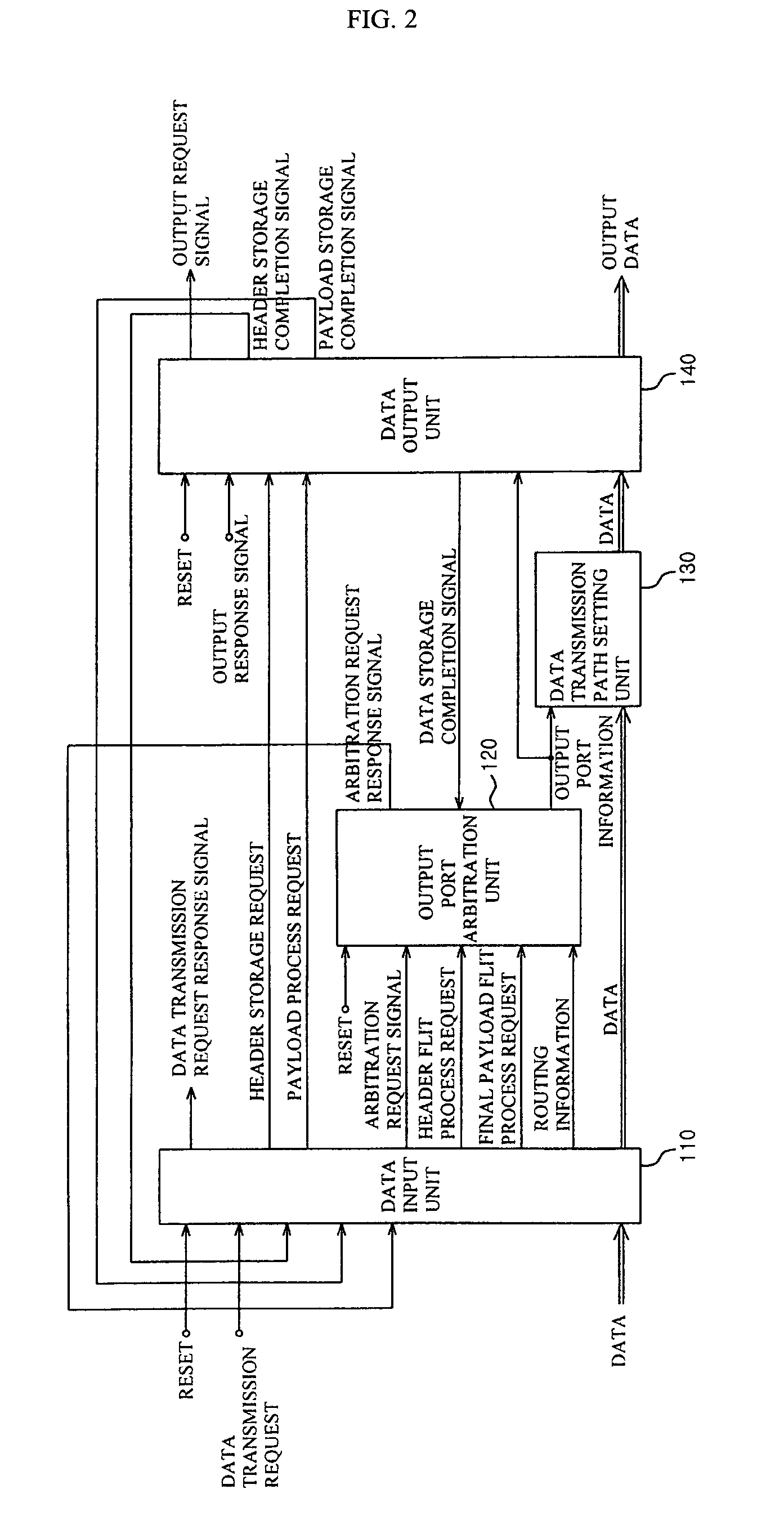
The present invention is related to asynchronous switches for network on chip applications. The invention provides an asynchronous switch based on a butterfly fat-tree topology that allows communication between IPs (Intellectual Properties) in the network on chip. The switch has several features such as a data input unit, output port arbitration unit, data transmission path setting unit, and data output unit. The switch uses a 4-stage bundled data protocol and a handshake protocol for synchronization. The butterfly fat-free topology is suitable for transmitting / receiving a variable length flit. The technical effects of the invention include improved performance, simplified control logic circuit, and efficient data transmission.

Problems solved by technology

Moreover, a worm hole switching means that when one data packet is transferred divided into a plurality of flits, it does not allow another data packet to be transferred through the same data transmission path by occupying a data transmission path during a transmission of the first flit to the final flit.

Method used


Image

  • Asynchronous switch based on butterfly fat-tree for network on chip application
  • Asynchronous switch based on butterfly fat-tree for network on chip application
  • Asynchronous switch based on butterfly fat-tree for network on chip application

Examples


Embodiment Construction

[0037]Preferred embodiments of the present invention will be described below in more detail with reference to the accompanying drawings. The present invention may, however, be embodied in different forms and should not be constructed as limited to the embodiments set forth herein. Rather, these embodiments are provided so that this disclosure will be thorough and complete, and will fully convey the scope of the invention to those skilled in the art. Like numerals refer to like elements throughout the specification.

[0038]Hereinafter, it will be described about an exemplary embodiment of the present invention in conjunction with the accompanying drawings.

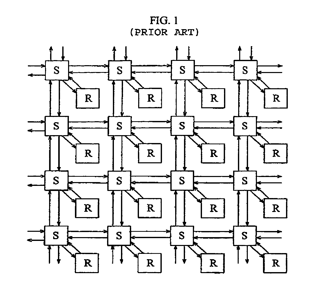
[0039]As shown in FIG. 1, one IP (R) is connected to one switch S. In this network on chip structure, one switch S should have five input / output ports and performs a function of transferring a packet inputted by a decided routing algorithm into a destination. In this case, since traffic becomes lager along with approach to the center ...


PUM


Abstract

The present invention disclosed herein is an asynchronous switch for an network on chip application making possible between IP (Intellectual Property) communication among various IPs in the network on chip. The asynchronous switch according to the present invention in which comprises a data input unit for receiving and storing a plurality of data flits, and confirming whether a kind of each data flit is a header flit or a payload flit according to a transmission request signal; an output port arbitration unit for outputting an output port selection signal showing a output priority of the data by receiving a header flit request signal, final payload flit process request signal, routing information of the header flit, and the a arbitration request signal from the data input unit; and a data output unit for receiving a header storage request signal and a payload storage request signal from the data input unit, temporarily storing the data flit inputted from the data transmission path setting unit, transferring header and payload storage completion signals indicating that the data flit is stored to the data input unit, and outputting the temporarily stored data flit to a designated port according to a pre-set order.

Description

CROSS-REFERENCE TO RELATED APPLICATIONS[0001]The present application claims priority to Korean patent application number 10-2004-0040205 filed on, Jun. 3, 2004 and Korean patent application number 10-2004-0068270 filed on Aug., 30, 2004 which are incorporated herein by reference in their entirety.BACKGROUND[0002]In order to catch up with a fast increasing multimedia function, system on chip SoC technique in which millions of gates are embodied on one chip is necessary. The SoC is a semiconductor integration circuit in which main functions of the system are integrated on one chip. The SoC includes all hardware and software functions needed for a system, such as a memory, a processor, an external interface, analog and hybrid mode block, built-in software, an OS and so forth.[0003]The SoC has an interconnection structure in which all components share one bus for intercommunication. However, there is a disadvantage of slow communication speed between the components. In addition, since s...

Claims


Application Information

Patent Timeline
Patent Type & Authority Patents(United States)
IPC IPC(8): G06F17/50G06F9/45H04L12/56
CPCH04L47/24H04L49/10H04L49/109H04L49/9042H04L49/15H04L49/251H04L49/112
Inventor KANG, MIN-CHANGJUNG, EUN-GUHAR, DONG-SOO
Owner GWANGJU INST OF SCI & TECH
Learn More