End cap warning signal assembly

a technology of warning signal and end cap, which is applied in the direction of identification means, instruments, lighting support devices, etc., can solve the problems of increasing the size of the light support, adversely affecting the aerodynamic characteristics of the vehicle, and relying on mechanical components to revolve, etc., to achieve simple and inexpensive design, operation, and long life cycle

Inactive Publication Date: 2008-12-23
SAFARILAND
View PDF73 Cites 31 Cited by
  • Summary
  • Abstract
  • Description
  • Claims
  • Application Information

AI Technical Summary

Benefits of technology

[0026]A principal advantage of the present invention is to provide an end cap warning signal assembly capable of simulating revolving or oscillating light signals without the use of mechanical components.
[0027]Another principal advantage of the present invention is that the end cap warning signal assembly is capable of producing several different light signals or combinations or patterns of light signals.
[0028]Still another principal advantage of the present invention is to be rugged and to have a relatively longer life cycle than traditional end cap warning signal assemblies.
[0029]Still another principal advantage of the present invention is to produce a truer or pure light output color without the use of filters.
[0030]Still another principal advantage of the present invention is to allow the user to adjust the color of the light signal without having to make a physical adjustment to the light source from a multi-colored panel.
[0031]Still another principal advantage of the present invention is the provision of an LED end cap warning signal assembly which is formed of a relatively simple and inexpensive design, construction, and operation and which fulfills the intended purpose without fear of failure, or risk of injury to persons and / or damage to property.

Problems solved by technology

Many problems exist with the known methods for producing warning light signals.
One particular problem with known light sources is their reliance on mechanical components to revolve or oscillate the lamps to produce the desired light signal or lighting effect.
Additionally, these components increase the size of the light support which may adversely affect the vehicles aerodynamic characteristics.
Moreover, because of the relatively poor reliability of conventional lighting, and the complexity of the present strobe rotational systems, there is an increased likelihood that a breakdown of the light source will occur, requiring the repair or replacement of the defective component.
Finally, conventional light sources require a relatively large amount of electrical current during operation.
The demands upon the electrical power system for a vehicle may therefore exceed available electrical resources, reducing optimization of performance or worse, generating a potential hazard from shorted or over heated systems.
Halogen lamps or gaseous discharge xenon lamps generally emanate large amounts of heat which is difficult to dissipate from a sealed light enclosure or emergency light and which may damage the electronic circuitry contained therein.
In addition, these lamps consume large amounts of current requiring a large power supply, battery, or electrical source which may be especially problematic for use with a vehicle.
These lamps also generate substantial electromagnetic emissions which may interfere with radio communications for a vehicle.
Finally, these lamps, which are not rugged, have relatively short life cycles necessitating frequent replacement.
Another problem with the known warning signal lights is the use of filters to produce a desired color.
Furthermore, filters fade or flake over time rendering the filters unable to consistently produce a desired color for observation in an emergency situation.
These problems associated with traditional signaling lamps are exacerbated by the fact that creating multiple light signals requires multiple signaling lamps.
Further, there is little flexibility in modifying the light signal created by a lamp.
For example, changing a stationary lamp into one that rotates or oscillates would require a substantial modification to the light support which may not be physically or economically possible.
Another problem with the known warning signal lights is the use of rotational and / or oscillating mechanisms which impart rotational or oscillating movement to a light source for observation during emergency situations.
These mechanical devices are frequently cumbersome and difficult to incorporate and couple onto various locations about a vehicle due to the size of the device.
These mechanical devices also frequently require a relatively large power source to impart rotational and / or oscillating movement for a light source.
Another problem with the known warning signal lights is the absence of flexibility for the provision of variable or modulated illumination intensity for the light sources to increase the number of available distinct and independent visual light effects.
Current end cap warning signal assemblies are generally limited to light signals produced by rotational and / or oscillating mechanisms which impart rotational or oscillating movement to a light source for observation during emergency situations.
Observation from the sides, or at an acute angle relative to the sides, frequently resulted in reduced observation of emergency lights during an emergency situation.

Method used


Image

  • End cap warning signal assembly
  • End cap warning signal assembly
  • End cap warning signal assembly

Examples


Embodiment Construction

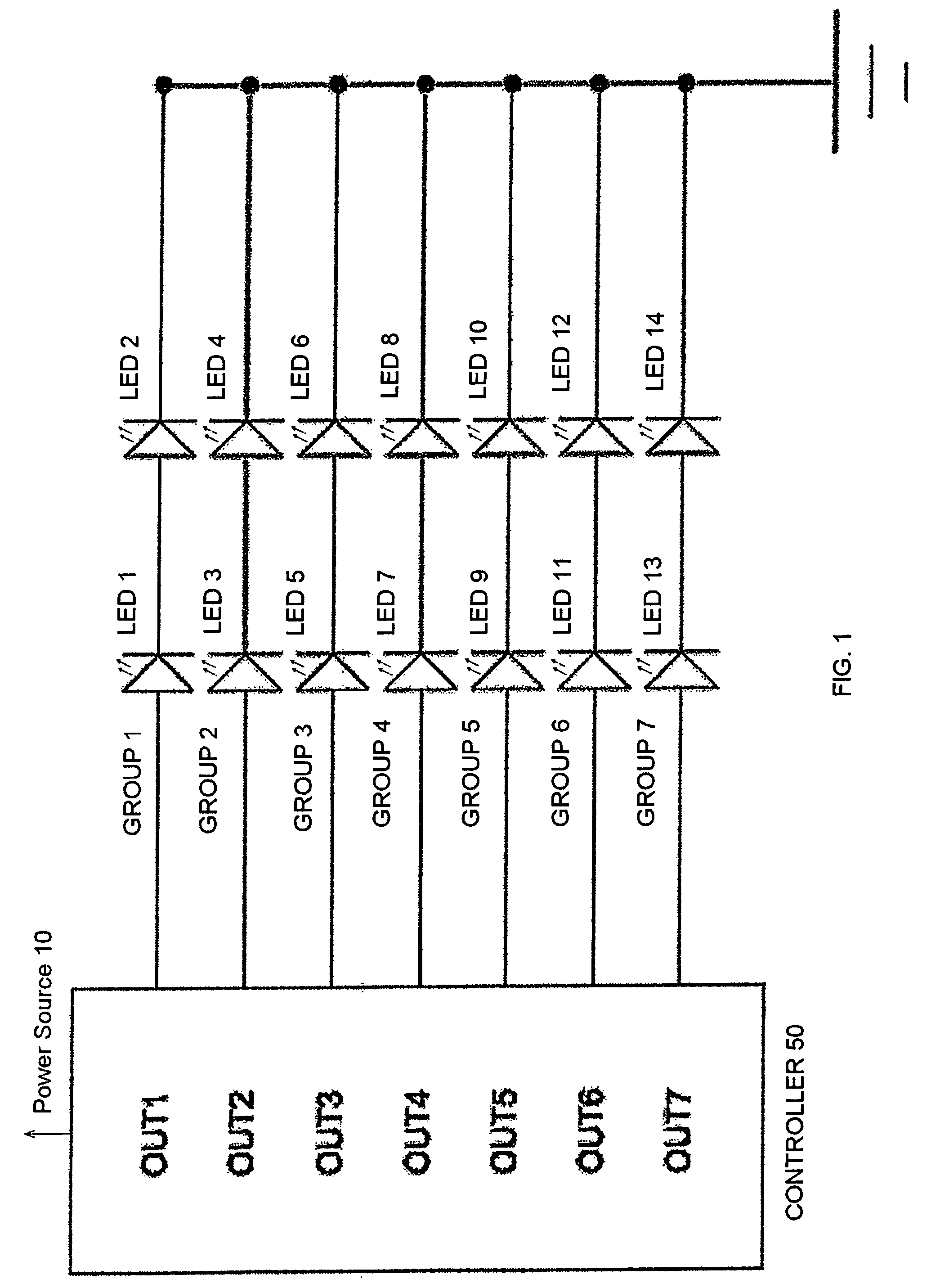
[0058]FIG. 1 shows an embodiment of generic controller 50 in electric communication with LEDs 1-14. Although not depicted in FIG. 1, controller 50 generally may comprise a microprocessor as well as additional electronics components, such as transistors, resistors, diodes, oscillators, capacitors, and voltage regulators that one skilled in art would recognize how to connect in order to control the LEDs 1234.

[0059]Controller 50 may include a memory device that stores any firmware code used to illuminate the LEDs 1234. The memory element may be a separate electronic component, such as an EEPROM, FlashRAM, or any other memory devices known by those skilled in the art. The memory element may alternatively be a part of the microcontroller itself, thereby reducing the overall footprint of the controller 50 by reducing the number of individual components.

[0060]As seen in FIG. 1, controller 50 is used to activate groups of LEDs 1234 that are electrically connected in series, the controller 5...


PUM


Abstract

A light emitting diode (LED) end cap warning signal assembly is disclosed. The end cap warning signal assembly includes a controller for generating a warning signal that simulates a rotating warning light signal. The end cap warning signal assembly further includes an integer number of M-LEDs arranged in an integer number of N-LED groups, with each LED having a duty cycle and at least 6 states. The controller activates each group of LEDs sequentially in an activation sequence

Description

[0001]The present invention is a Continuation-In-Part Application of, and claims priority to, U.S. patent application Ser. No. 10 / 688,515 filed Oct. 17, 2003, which is a Continuation-In-Part of, and claims priority to, U.S. patent application Ser. No. 10 / 625,387 filed Jul. 23, 2003, which is a Continuation-In-Part Application of, and claims priority to, U.S. patent application Ser. No. 10 / 017,348 filed Dec. 14, 2001, now issued U.S. Pat. No. 6,623,151 issued Sep. 23, 2003, which is a utility patent application claiming priority to U.S. Provisional Patent Application Ser. No. 60 / 292,470 filed May 21, 2001, and which is a Continuation-In-Part of U.S. utility application Serial No. 09 / 627,867 filed Jul. 28, 2000, now issued U.S. Pat. No. 6,461,008 issued Oct. 8, 2002, which claimed priority to U.S. provisional application Ser. No. 60 / 147,240 filed Aug. 4, 1999, all of which are incorporated herein by reference in their entireties.BACKGROUND OF THE INVENTION[0002]Emergency lights of the...

Claims


Application Information

Patent Timeline
Patent Type & Authority Patents(United States)
IPC IPC(8): G09F9/33
CPCB60Q1/2611B60Q1/2696F21V33/0076G09F9/33H05B33/0842H05B37/029F21V29/004F21Y2101/02F21V29/763F21Y2115/10H05B45/32H05B47/155
Inventor PEDERSON, GREGORY A.BRANAN, EDWARD R.
Owner SAFARILAND
Why Eureka
Try Eureka