
Pipe fitting comprising at least two layers of different material, the innermost layer made of plastic

a technology of pipe fittings and different materials, applied in the direction of hose connections, branching pipes, bends, etc., can solve the problems of difficult to keep the system clean, the outer layer is not easily attached to the hard material, etc., and achieves good oxygen diffusion protection and uv protection of the pipe fittings, low manufacturing cost, and good chemical resistance

Inactive Publication Date: 2008-12-30
UPONOR INNOVATION AB
View PDF30 Cites 3 Cited by
  • Summary
  • Abstract
  • Description
  • Claims
  • Application Information

AI Technical Summary

Benefits of technology

[0008]Advantage of the invention is that the manufacturing costs of the pipe fitting are low. Further, oxygen diffusion protection and UV protection of the pipe fitting are very good, which is important when, for example, parts are stored on construction sites for long times and pipe fittings are used in surface mounting. The pipe fitting can be provided with an extremly good chemical resistance. Further, it is simple and easy to modify the appearance of the pipe fitting. It is also easy to make the impact resistance of the pipe fitting extremely good. When the different layers are not attached to each other, the pipe fitting is very resistant to shear stress. This is because the surface that are moving / separate relative to each other transfer forces more flexibly and more advantageously. The different layers of the pipe fitting can be formed at different times, because it is not desirable that the different layers become attached to each other. Hence, forming the production process of the pipe fitting is reasonably simple. Further, the material of the innermost layer can be selected to be rather hard, whereby the outer layer is not easily attached to the hard material. The material of the inner layer is perferably very hard in order for it to bore into the softer inner wall of the pipe to be fitted upon implemention of the fitting, and to form a tight fitting. Forming a stop member of the end of the outer layer makes the connecting of the pipe to the pipe fitting easy, and thus, a tight and reliable fitting is ensured. In addition, since the end of the outer layer functions as the stop member, no other stop member is required that would make it difficult to keep the system clean, for instance.
is that the manufacturing costs of the pipe fitting are low. Further, oxygen diffusion protection and UV protection of the pipe fitting are very good, which is important when, for example, parts are stored on construction sites for long times and pipe fittings are used in surface mounting. The pipe fitting can be provided with an extremly good chemical resistance. Further, it is simple and easy to modify the appearance of the pipe fitting. It is also easy to make the impact resistance of the pipe fitting extremely good. When the different layers are not attached to each other, the pipe fitting is very resistant to shear stress. This is because the surface that are moving / separate relative to each other transfer forces more flexibly and more advantageously. The different layers of the pipe fitting can be formed at different times, because it is not desirable that the different layers become attached to each other. Hence, forming the production process of the pipe fitting is reasonably simple. Further, the material of the innermost layer can be selected to be rather hard, whereby the outer layer is not easily attached to the hard material. The material of the inner layer is perferably very hard in order for it to bore into the softer inner wall of the pipe to be fitted upon implemention of the fitting, and to form a tight fitting. Forming a stop member of the end of the outer layer makes the connecting of the pipe to the pipe fitting easy, and thus, a tight and reliable fitting is ensured. In addition, since the end of the outer layer functions as the stop member, no other stop member is required that would make it difficult to keep the system clean, for instance.

Problems solved by technology

The different layers of the pipe fitting can be formed at different times, because it is not desirable that the different layers become attached to each other.
Further, the material of the innermost layer can be selected to be rather hard, whereby the outer layer is not easily attached to the hard material.
In addition, since the end of the outer layer functions as the stop member, no other stop member is required that would make it difficult to keep the system clean, for instance.

Method used


Image

  • Pipe fitting comprising at least two layers of different material, the innermost layer made of plastic
  • Pipe fitting comprising at least two layers of different material, the innermost layer made of plastic

Examples


Embodiment Construction

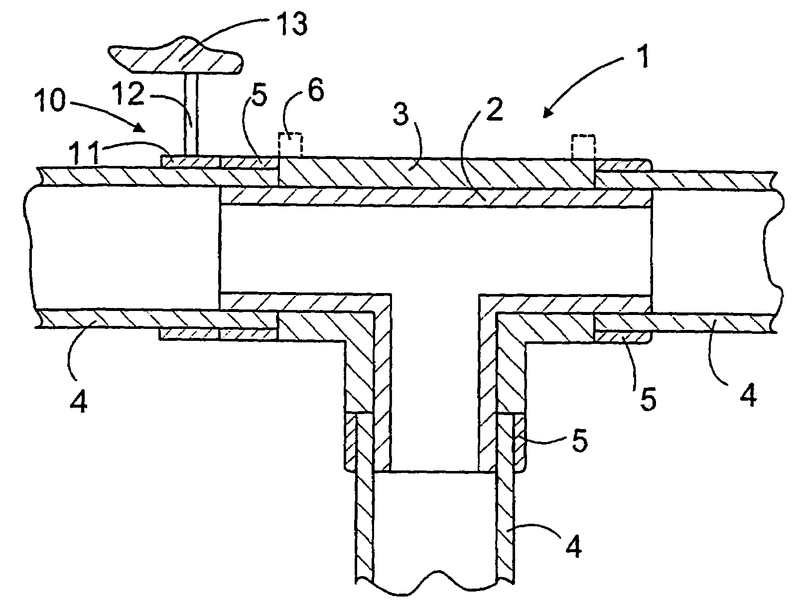
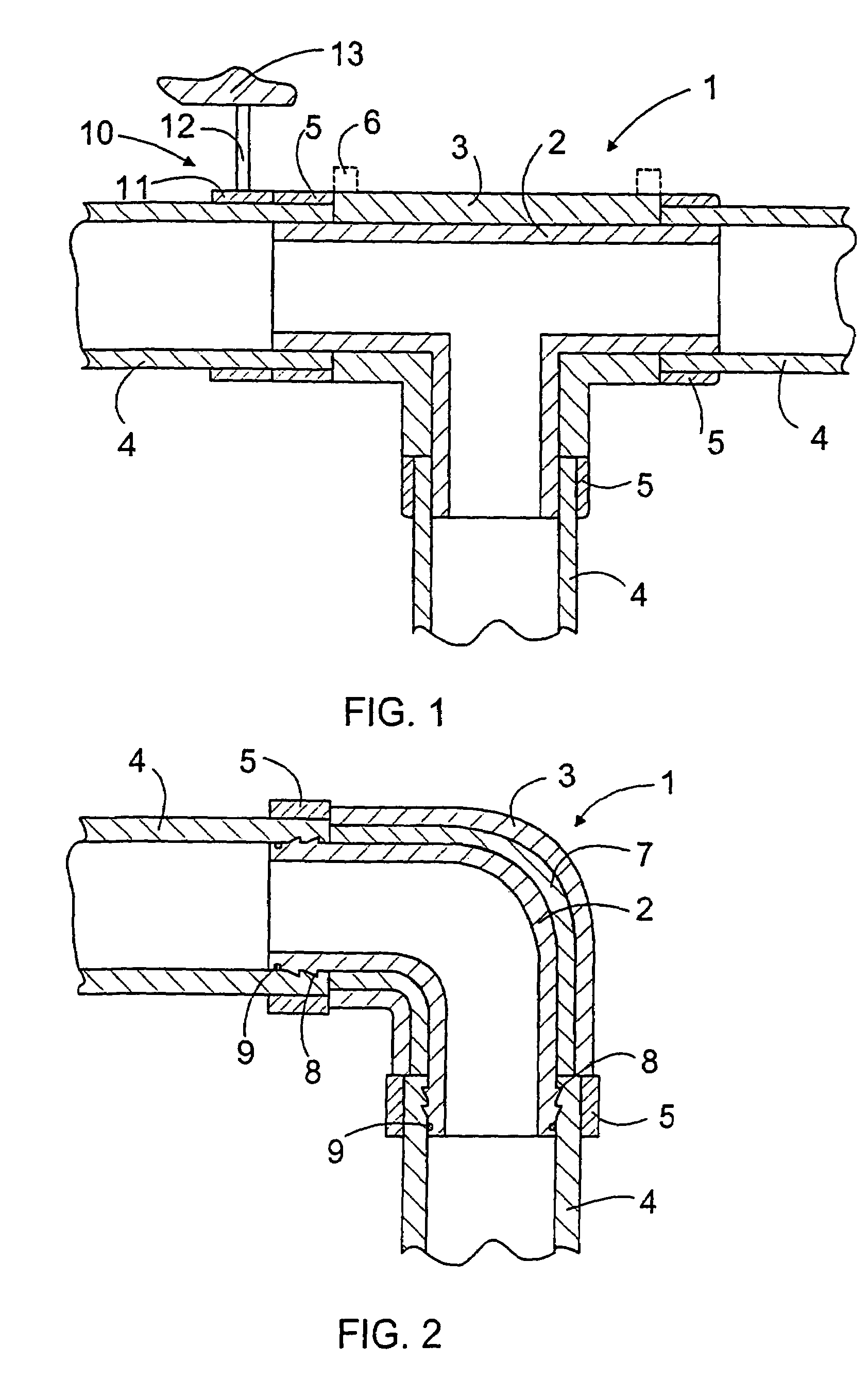
[0012]FIG. 1 shows a pipe fitting 1, more precisely a single branch. The pipe fitting frame comprisies an innermost layer 2 and outer layer 3 outside it. The pipe fitting 1 is used to connect pipes 4 to each other. The pipes are plastic pipes or composite pipes comprising a plastic innermost layer and metal outside it, for example a layer made of aluminium. Outside the metal layer, there may further be a plastic layer, for instance. The end of the pipe fitting 1 is arranged inside the end of the pipe 4, and the connection can still be reinforced with a compression collar 5. The pipe fitting 1 is intended to be used in hot-water and domestic water pipe systems, for instance. The pipe fitting 1 can also be used in pneumatic or industrial systems. Thus, the innermost layer 2, which gets into contact with the liquid to be conveyed, is made of a material tolerating high temperatures, such as polyphenyl sulphone PPSU or polysulphone PSU. Typically, the innermost layer material must tolera...


PUM

PropertyMeasurementUnit
temperatureaaaaaaaaaa
pressureaaaaaaaaaa
temperatureaaaaaaaaaa

Abstract

A pipe fitting for connecting at least two pipes, the pipe fitting (1) comprising at least two layers. An innermost layer (2) and an outer layer (3) are of different materials. The innermost layer (2), which gets into contact the liquid to be conveyed, is made of plastic tolerating high temperatures. The outer layer (3) is formed of such materials that the outer surface is arranged to function as the provider of oxygen diffusion protection and / or the UV protector.

Description

FIELD OF THE INVENTION[0001]The invention relates to a pipe fitting for connecting at least two pipes.BACKGROUND OF THE INVENTION[0002]Plastic hot-water pipe systems and domestic water pipe systems are usually intended to be mounted inside a structure, such as a partition floor or a partition wall, by using protecting tubes. The pipe fittings are made to be of a colour different from the pipes, whereby they are clearly different from each other. Further, pipe fittings are typically provided with reinforcing ribs and other irregularities on the outer surface, which causes the fittings to gather dirt and makes it extremely difficult to keep the outer side of the pipe systems clean.[0003]Solutions for connecting pipes to each other are disclosed in publications DE 19 735 919, DE 29 814 047 and DE 29 907 585, for example. The publications describe a solution comprising a pipe fitting made of metal or plastic, the end of which is arranged inside the pipe to be connected. A compression sl...

Claims


Application Information

Patent Timeline
Patent Type & Authority Patents(United States)
IPC IPC(8): F16L33/00F16L47/24
CPCF16L47/24
Inventor SMAHL, JARMO
Owner UPONOR INNOVATION AB
Learn More