High-frequency balun

a high-frequency balun and balun technology, applied in the field of balun, can solve the problem of narrowing the band width of the transmission frequency fsub>0 /sub>

Inactive Publication Date: 2008-12-30
NIHON DEMPA KOGYO CO LTD
View PDF3 Cites 12 Cited by
  • Summary
  • Abstract
  • Description
  • Claims
  • Application Information

AI Technical Summary

Benefits of technology

[0011]Accordingly, it is an object of the present invention to provide a high-frequency balun having a flat propagation characteristic across a wide band without losing the band width of the transmission frequency during the mutual-conversion between the balanced line and the unbalanced line.
[0014]According to this arrangement, first, the microstrip line as the unbalanced line is electromagnetically coupled to the slot line, and the high-frequency wave component travels from the microstrip line to the slot line. Then, the slot line is electromagnetically coupled to the microstrip line as the balanced line at the central portion of the microstrip line. Therefore, the high-frequency component branches from the central point of the microstrip line as the balanced line in opposite-phase and travels toward both ends of the microstrip line. Therefore, the unbalanced line can be converted to the balanced line. Needless to say, the balanced line can be converted to the unbalanced line. According to this arrangement, since the slot line is used, basically, the bandwidth of the transmission frequency can be made wider and the transmission characteristic within the passing band can be made flat.
[0017]In the present invention, an end portion that functions as the electric short-circuited end of the microstrip line may project to provide an electric length of λ / 4 from a traversing point (i.e., crossing point) to the slot line relative to a wavelength of λ corresponding to a transmission frequency. With this arrangement, the energy conversion efficiency from the microstrip line to the slot line in the transmission frequency can be enhanced.
[0018]Alternatively, the end portion that functions as the electric short-circuited end of the microstrip line may be constructed by electrically connecting a signal line and a ground conductor of the microstrip line by an electrode through-connection such as a via-hole or through-hole. This arrangement provides an electric short-circuited end for wide frequency bands, there is no frequency selectivity, and therefore the bandwidth of the transmission frequency can be made wider.
[0019]In the balun according to the present invention, preferably, both ends of the slot line function as electric open ends. With this arrangement, the energy conversion efficiency from the microstrip line to the slot line can be enhanced.
[0020]The both end portions of the slot line may project to provide an electric length of λ / 4 from a traversing point with the microstrip line relative to a wavelength of λ corresponding to a transmission frequency. With this arrangement, the energy conversion efficiency can be enhanced.

Problems solved by technology

Therefore, as shown in FIG. 2, single peak characteristic (curve L) is obtained after conversion, while transmission frequency characteristic (curve K) having a linear property is provided before conversion, and there is a problem in that the band width of transmission frequency f0 is narrowed.

Method used


Image

  • High-frequency balun
  • High-frequency balun
  • High-frequency balun

Examples


first embodiment

[0043]FIGS. 4A and 4B show a high-frequency balun according to the first embodiment of the present invention. In FIGS. 4A and 4B, the same reference numerals are applied to the same elements as FIGS. 1A and 1B, and no redundant explanations are repeated.

[0044]A balun according to the first embodiment and baluns according to the second and third embodiments, which will be described later, are basically configured by using slot line 9 for converting a balanced line to an unbalanced line and vice versa. A balun according to the first embodiment includes: substrate 4 made of a dielectric material or the like; microstrip lines 10, 11 each having a signal lines formed in one main surface of substrate 4; ground conductor 5 formed on the whole of the other main surface of substrate 4; and slot line 9 arranged by forming an opening in ground conductor 5. Microstrip line 10 is a microstrip line of the unbalanced line for input / output in unbalanced mode. In this specification, we call microstr...

second embodiment

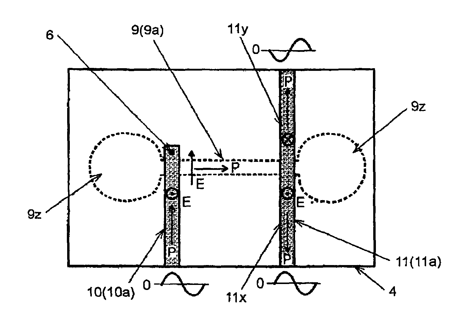
[0052]Next, explanations are given of a balun according to the second embodiment of the present invention with reference to FIGS. 7A to 7c. In FIGS. 7A to 7c, the same reference numerals are applied to the same elements as FIGS. 4A and 4B.

[0053]In the balun according to the first embodiment, one balanced microstrip line 11 is arranged and high-frequency wave components in opposite-phase each other are obtained from both ends of balanced microstrip line 11, whereby the high-frequency component in balanced mode is obtained. However, in the balun according to the second embodiment, a pair, namely, two balanced microstrip lines 11x, 11y are arranged, both balanced microstrip lines 11x, 11y are used as a balanced transmission line as a whole, and a high-frequency component in balanced mode is obtained.

[0054]In the balun according to the second embodiment, the other end portion of unbalanced microstrip line 10 traverses or crosses the center portion (center point) of slot line 9 that exte...

third embodiment

[0058]A balun according to the third embodiment of the present invention shown in FIG. 8 is similar to that of the first embodiment, however, the balun according to the third embodiment is different from that of the first embodiment in an arrangement for setting the tip portion of unbalanced microstrip line 10 to an electrical short-circuited end and an arrangement for setting both ends of slot line 9 to electric open ends.

[0059]In the third embodiment, the tip end of unbalanced microstrip line 10 projects from the traversing point of slot line 9 is connected to ground conductor 5 by via-hole 6 that is arranged adjacently to the traversing point. Also, both ends of slot line 9 that project from the traversing points of unbalanced microstrip line 10 and balanced microstrip line 11 are formed so as to be wider than the width of slot line 9 in the portion between these two traversing points, that is, the width of aperture line 9a in ground conductor 5. In this embodiment, both ends of ...


PUM


Abstract

In a balun for mutually converting an unbalanced line for unbalanced input / output and a balanced line for balanced input / output, the unbalanced line and the balanced line are microstrip lines including a signal line arranged on one main surface of a substrate and a ground conductor arranged on the other main surface of the substrate. The balun further includes a slot line formed by a aperture line arranged in the ground conductor in the other main surface. The microstrip line as the unbalanced line includes one end portion used as an input / output end and the other end portion that traverses the slot line, electromagnetically couples to the slot line, and functions as an electric short-circuited end. The central portion of the microstrip line as the balanced line traverses the slot line and electromagnetically couples to the slot line. Both ends of this microstrip line serves as the input / output ends.

Description

BACKGROUND OF THE INVENTION[0001]1. Field of the Invention[0002]The present invention relates to a balun used to mutually convert a unbalanced transmission line and a balanced transmission line, and in particular relates to a balun that is suitable for use in a high-frequency band, such as a microwave band and that attains a wider bandwidth.[0003]2. Description of the Related Art[0004]A balun is known as a transformer for converting from an unbalanced transmission line to a balanced transmission line and vice versa, and is used, for example, in an input / output end of a repeater in a communication system. Various baluns are known, and one of those is a high-frequency balun using a microstrip line (MSL) coupling line, known as an unbalanced high-frequency transmission line. In recent years, in optical communication systems or the like, information has been transmitted by using UWB (Ultra Wide Band) as a frequency band, for example, a frequency band from 3.1 to 10.6 GHz, and with this ...

Claims


Application Information

Patent Timeline
Patent Type & Authority Patents(United States)
IPC IPC(8): H01P5/10H01P3/08H01P5/12
CPCH01P5/10
Inventor ASAMURA, FUMIOKAWAHATA, KENJISAKAMOTO, KATSUAKI
Owner NIHON DEMPA KOGYO CO LTD
Why Eureka
Try Eureka