Information storage apparatus storing and reading information by irradiating a storage medium with electron beam

a technology of information storage and electron beam, which is applied in the direction of instruments, tubes with electrostatic control, non-electron-emitting shielding screens, etc., can solve the problems of difficulty in achieving a much higher density and the size of the apparatus itself, so as to achieve a greater degree of vacuum, reduce the size of the beam spot, and prevent the attachment of foreign objects and others.

Inactive Publication Date: 2008-12-30
PANASONIC CORP
View PDF21 Cites 7 Cited by
  • Summary
  • Abstract
  • Description
  • Claims
  • Application Information

AI Technical Summary

Benefits of technology

[0016]The cold cathode electron beam emitting part may include a cold cathode placed in a chamber surrounded by a partition and a film capable of transmitting an electron beam such that the inside of the chamber has a higher degree of vacuum than the outside thereof. In such a case, the degree of vacuum around a spindt-type cold cathode or carbon nanotubes, for example, is maintained and attachment of foreign matters and others are prevented with ease. Accordingly, even in the cases of a spindt-type cold cathode and a small number of carbon nanotubes, the beam spot size is more easily reduced so that the storage density is increased without decrease in stability of electron emission.
[0017]Furthermore, in a case where an accelerating part for accelerating an electron beam emitted from the cold cathode electron beam emitting part, a deflection part for deflecting the electron beam in one- or two-dimensional directions, and a convergence part for causing the electron beam to converge are provided with a given electric field or magnetic field generated, an electron beam may be accelerated in such a manner that a plurality of electrodes to which voltages with different phases are applied are provided and thereby a moving electric field is generated. The cold cathode electron beam emitting part may be configured in such a manner that a plurality of electron emitting parts are provided to emit electron beams at different timings according to the distance from a given center so that the emitted electron beams converge. With these configurations, the presence and absence of emission of an electron beam, the energy thereof and an irradiated position and an irradiated area on the storage medium, for example, are easily controlled.
[0018]To irradiate only a given region of the storage medium with an electron beam, an electron beam passing through a minute hole formed in a shielding part such as a plate member may be adjusted to reach the storage medium. If at least one of such a plate member and the storage medium is moved by an actuator using a so-called micromachine technology, reduction of an area of the storage medium irradiated with an electron beam and control of the irradiated position are also easily achieved. An electrode may be provided around the minute hole to form an electrolytic lens. Then, the efficiency in using an electron beam is enhanced and, in addition, a region irradiated with an electron beam is smaller than the diameter of the minute hole, thus further increasing the storage density.
[0020]An irradiated-position-shift detecting part for detecting a shift between a given reference position and a position in the storage medium irradiated with an electron beam may be provided so that the irradiated position is controlled by calibration or feedback control. Then, the accuracy in locating the irradiated position is enhanced, and the storage density is more easily increased.

Problems solved by technology

(1) The sizes of apparatuses themselves are large;
(2) Heaters and power supplies for the heaters are needed to emit thermoelectrons; and
(3) High voltages of about several thousand volts are required to emit electron beams.
However, semiconductor processes have constraints in fabrication, and therefore there arises the problem of difficulty in achieving a much higher density.

Method used


Image

  • Information storage apparatus storing and reading information by irradiating a storage medium with electron beam
  • Information storage apparatus storing and reading information by irradiating a storage medium with electron beam
  • Information storage apparatus storing and reading information by irradiating a storage medium with electron beam

Examples


Embodiment Construction

[0042]Hereinafter, embodiments of the present invention will be described with reference to the drawings.

[0043](Information Storage Apparatus Including One Information Storage Cell)

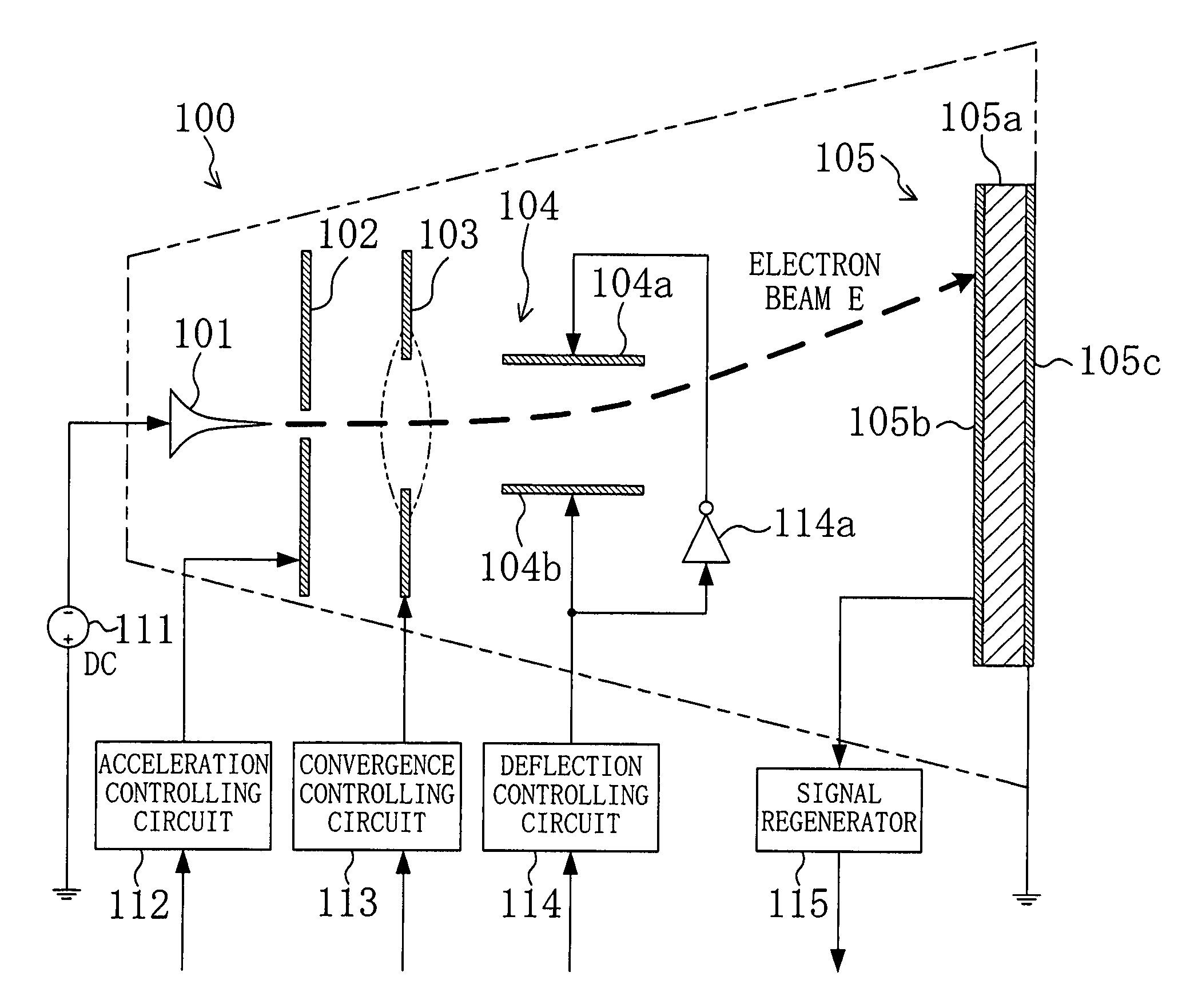
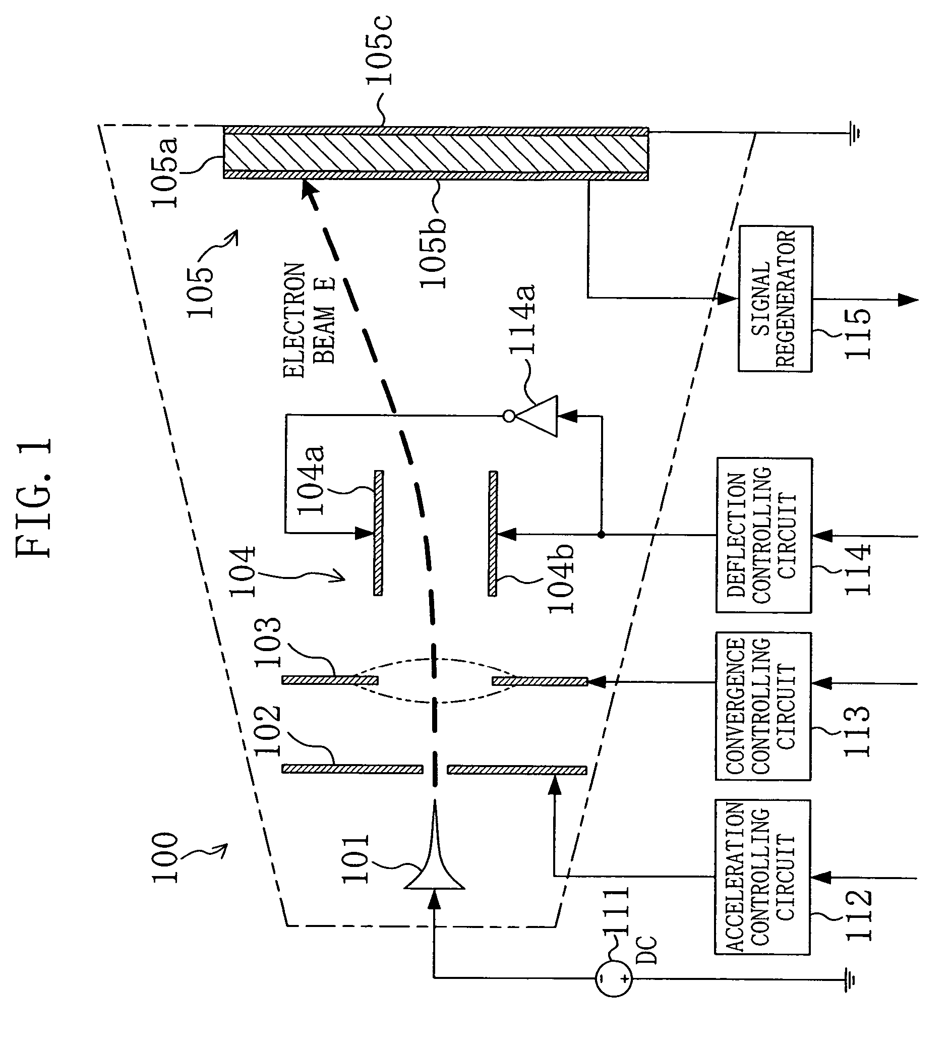
[0044]FIG. 1 is a view schematically showing a configuration of an information storage apparatus including one information storage cell 100.

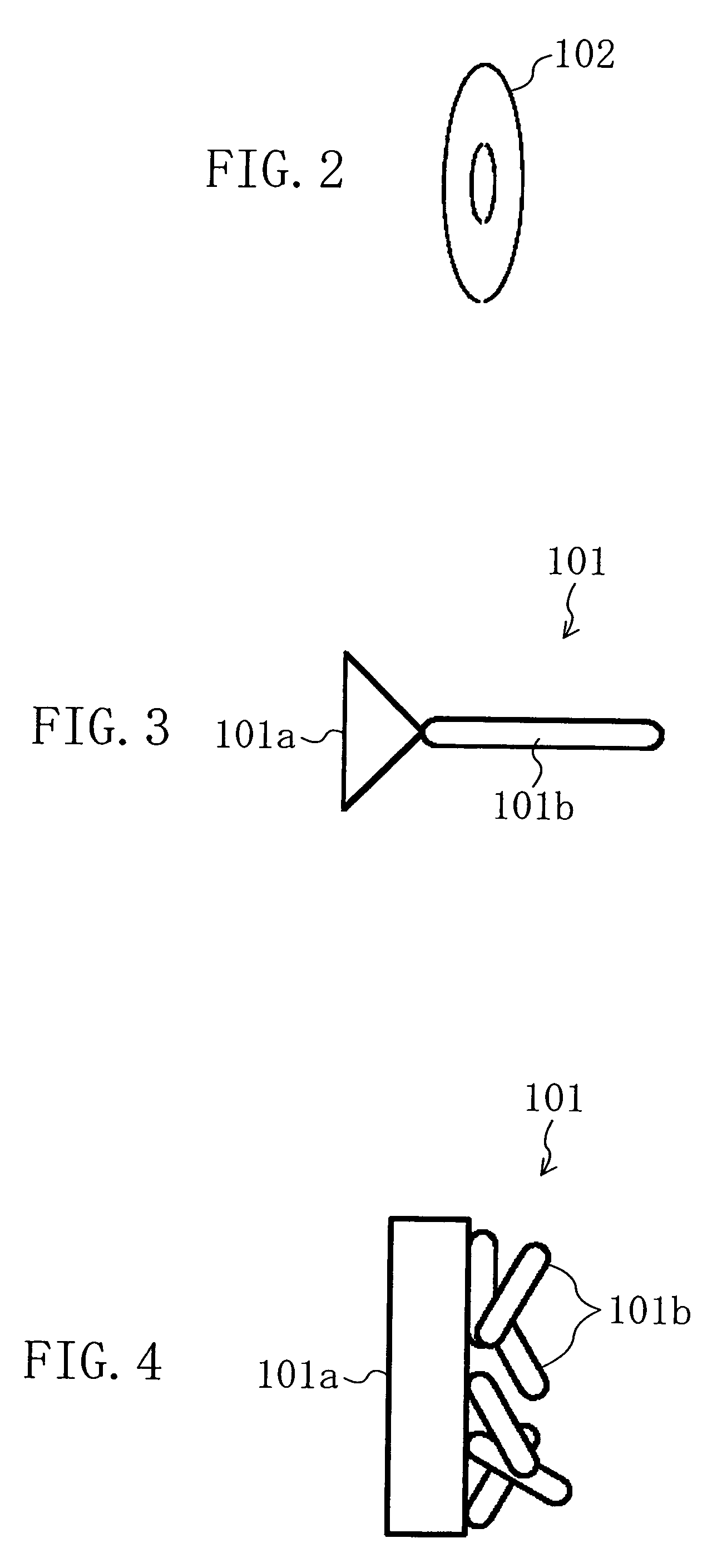
[0045]A cold cathode 101 emits an electron beam E upon application of a negative voltage from a cathode ray driver 111. The configuration of this cold cathode 101 will be specifically described later. The voltage applied to the cold cathode 101 may be a DC voltage or a pulse driving voltage such as surge pulses.

[0046]An accelerating electrode 102 is made of an annular electrode as shown in FIG. 2, for example, and receives, from an acceleration controlling circuit 112, a voltage higher than that applied to the cold cathode 101. The accelerating electrode 102 extracts electrons from the cold cathode 101 by utilizing an electric field generated between the accelerating ...


PUM


Abstract

To greatly increase the storage density of a storage apparatus, an electron beam E emitted from a cold cathode 101 is accelerated by an accelerating electrode 102, caused to converge by a convergence electrode 103, deflected by a deflection electrode 104 and applied to a minute region of a storage film 105. The storage film 105 includes, for example, a phase change film 105a. The film is rapidly heated and cooled to change into an amorphous state upon irradiation with an electron beam E with high energy, while being gradually cooled to change into a crystallized state upon irradiation with an electron beam E with approximately intermediate energy, thereby storing data. Upon irradiation with an electron beam E with low energy, the potential difference between a detection electrode 105b and an anode 105c is detected depending on the state, i.e., the amorphous or crystallized state, thereby reading stored data.

Description

TECHNICAL FIELD[0001]The present invention relates to a technique for an information storage apparatus that stores and reads information by irradiating a storage medium with an electron beam.BACKGROUND ART[0002]As an information storage apparatus that stores and reads information by irradiating a dielectric with an electron beam, an apparatus using a cathode ray tube (CRT) similar to that for display had been studied much before core memories and semiconductor memories were put into practical use (for example, U.S. Pat. No. 2,755,994, column 2, lines 19 to 56.) In this patent, as in the case of displaying an image, a voltage of negative several thousand volts is applied to a red hot filament so as to emit thermoelectrons, and a dielectric (phosphor) is irradiated with an electron beam of the thermoelectrons, thereby storing and reading information.[0003]More specifically, when a region of a dielectric associated with a storage bit is irradiated with a deflected electron beam, electr...

Claims


Application Information

Patent Timeline
Patent Type & Authority Patents(United States)
IPC IPC(8): G11C13/00G11C7/00G11C11/30H01J19/24H01J19/32H01J19/38H01J19/40H01J21/10
CPCG11C7/005
Inventor KANDA, YOSHIHIROMUSHIKA, YOSHIHIRO
Owner PANASONIC CORP
Why Eureka
Try Eureka