Folding seat

Inactive Publication Date: 2009-01-06
THE WISE
View PDF93 Cites 42 Cited by
  • Summary
  • Abstract
  • Description
  • Claims
  • Application Information

AI Technical Summary

Benefits of technology

[0039]A resultant moment is created due to at least a plurality of these regions of contact that resists any further rearward backrest movement, preventing over rotation. In a preferred embodiment, the resultant moment created by pawl and notch wall contact, by end wall to end wall contact, and boss and retaining element contact helps prevent further backrest rotation. Such an arrangement not only creates such an advantageous rotation opposing moment but also helps spread out the contact force between the backrest and base over a greater surface area reducing hinge or pivot joint wear.
[0040]Objects, features and advantages of the present invention include providing a seat equipped with a backrest constructed and arranged to accommodate a replaceable backrest panel, providing a seat having a f

Problems solved by technology

While many vehicle seats have been previously designed with integral backrests in order to provide a seat and backrest for an individual, the seats having integral non-folding backrests presented certain problems.
More specifically, the integral non-folding backrest interfered with the ability of individuals to move about the vehicle when performing certain activities on the vehicle, such as fishing, as well as complicating the storage of the vehicle due to the height of the backrests.
In addition the non-folding backrest of the seat, depending on the seat location in a boat, often impaired the visibility of the boat operator while driving.
While simple in construction, this design is costly because it is generally time consuming to make and assemble.
In addition, the metal hinges are typically exposed, which presents a significant pinch point that could injure a person when the seat is rotated in either direction.
While this design has reduced the likelihood of injury occurring while rotating the backrest, it has not significa

Method used


Image

  • Folding seat
  • Folding seat
  • Folding seat

Examples


Example

[0055]Before explaining one or more embodiments of the invention in detail, it is to be understood that the invention is not limited in its application to the details of construction and the arrangement of the components set forth in the following description or illustrated in the drawings. The invention is capable of other embodiments, which can be practiced or carried out in various ways. Also, it is to be understood that the phraseology and terminology employed herein is for the purpose of description and should not be regarded as limiting.

DETAILED DESCRIPTION OF AT LEAST ONE PREFERRED EMBODIMENT

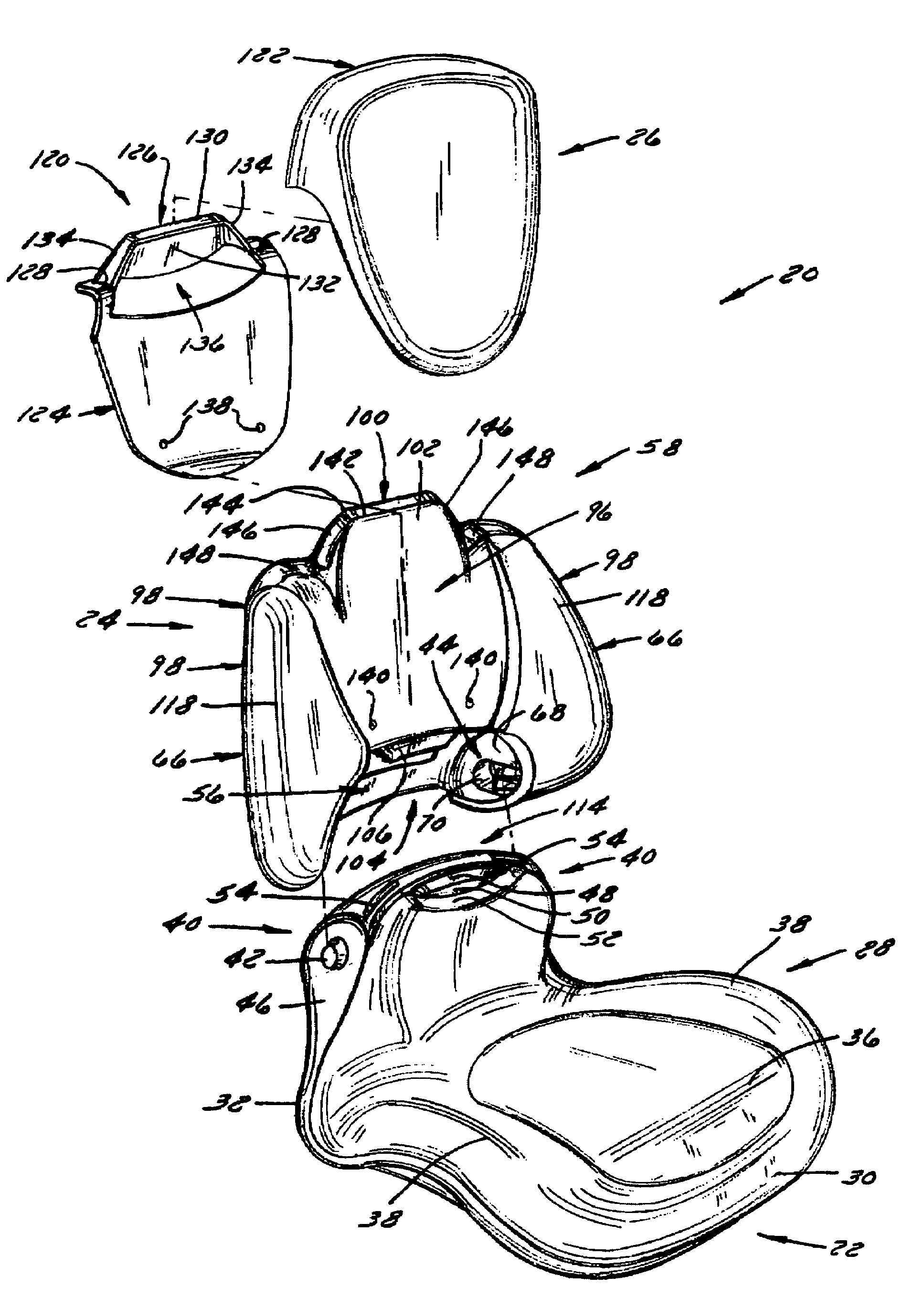
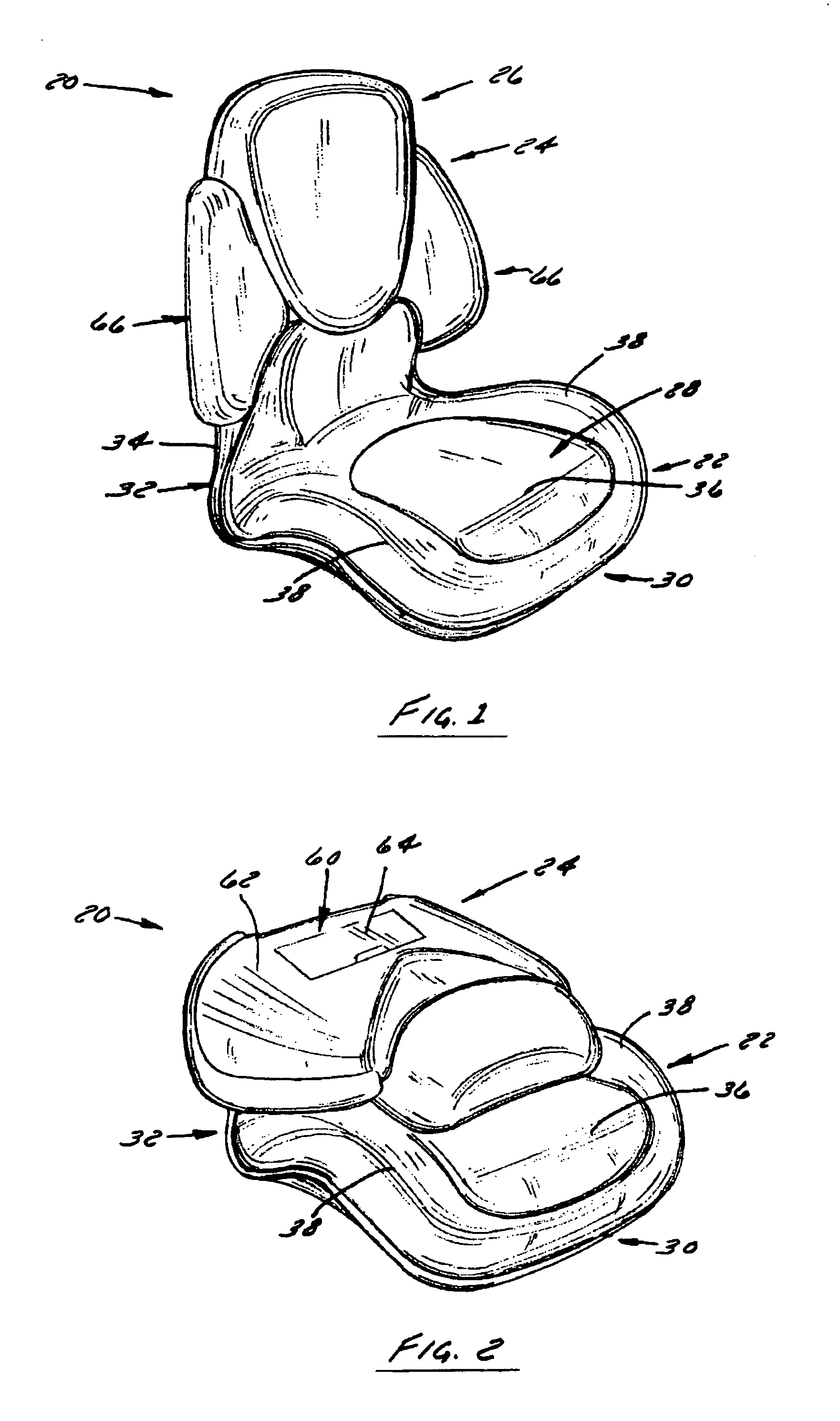
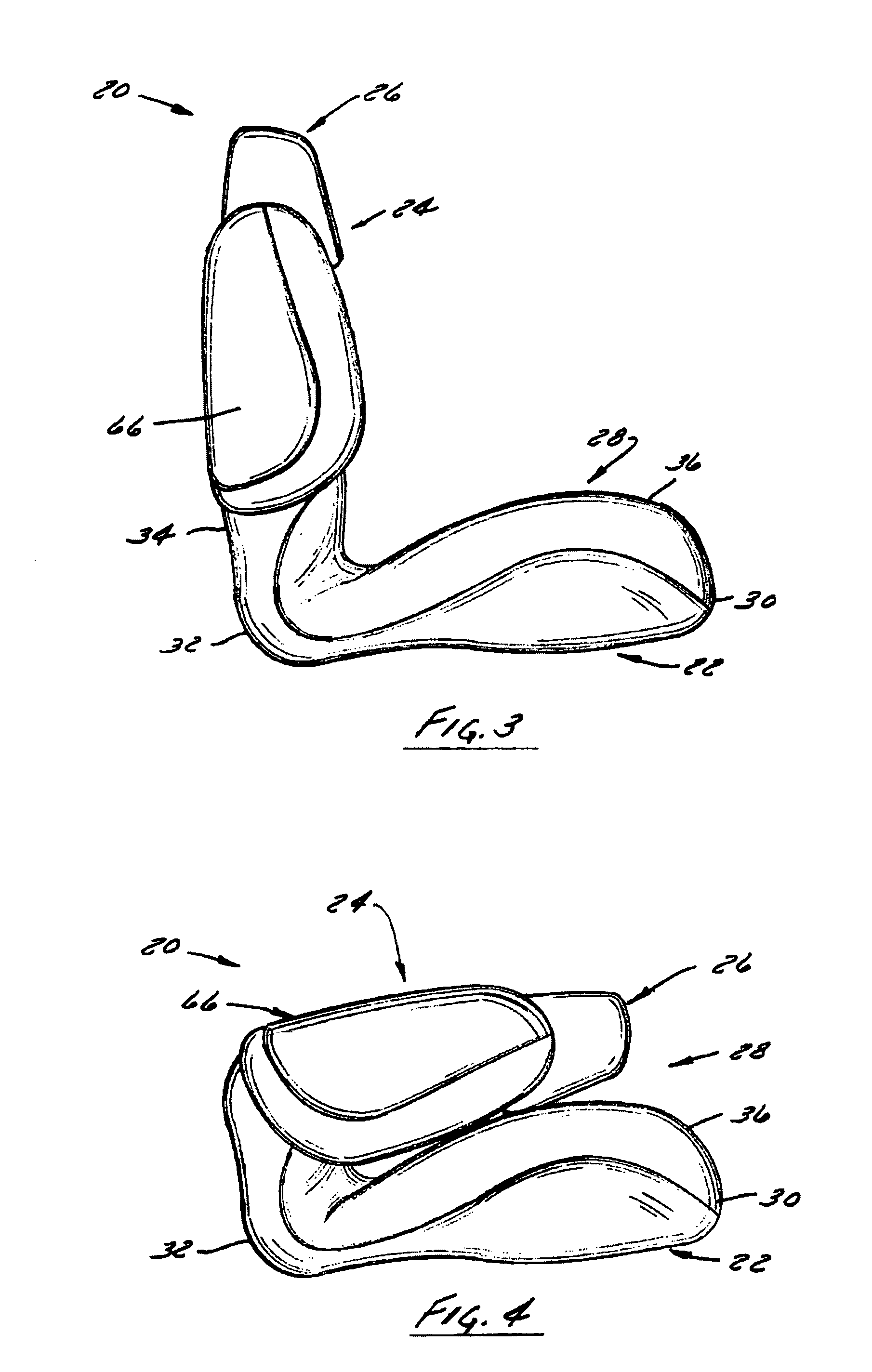
[0056]With reference now to the drawing figures in which like reference numerals designate like parts throughout the disclosure, a folding chair or seat is indicated generally by reference numeral 20 in FIG. 1. The seat 20 includes a base 22, a backrest 24 attached to the base 22, and a backrest center panel assembly 26 carried by the backrest 24. The base 22 can be attached to the floor ...


PUM


Abstract

A modular folding seat for use in vehicles is provided. The seat includes a base securable to the vehicle; a backrest pivotally connected to the base, and can include a removable backrest panel mounted to the backrest. The base or the backrest includes a pair of outwardly extending bosses disposed on opposite sides that are rotatably engageable within recesses disposed in the other one of the base or backrest. The bosses are held within the recesses by a pair of engagement members disposed adjacent or in each recess. The engagement members are capable of being deflected to a non-securing position whereby the bosses can be inserted into or withdrawn from the recesses to assemble or disengage the backrest to or from the base. A plurality of regions of engagement between the base and backrest keep the backrest from over rotating beyond a fully upright position and resist downward folding of the backrest when in the upright position. Another engagement region can be provided to park the backrest in a downwardly folded position.

Description

CROSS-REFERENCE TO RELATED APPLICATION[0001]This application claims the benefit of and priority under 35 U.S.C. Section 119(e) to U.S. Provisional Application Ser. No. 60 / 570,734, filed May 12, 2004, the entirety of which is hereby expressly incorporated herein by reference.FIELD OF THE INVENTION[0002]The present invention relates to seats or chairs, and more specifically to foldable seats or chairs designed for use with recreational vehicles, such as boats, watercraft, and the like.BACKGROUND OF THE INVENTION[0003]In recreational vehicles, such as boats and other watercraft, chairs or seats are often utilized in order to enable individuals to sit comfortably in or on the vehicle while the vehicle is in operation. To enhance the ability of the seat to provide a comfortable and stable seating surface for an individual onboard the vehicle, numerous vehicle seats have also been supplied with foam pads which are contacted by an individual resting on the seat to both provide a soft surfa...

Claims


Application Information

Patent Timeline
IPC IPC(8): A47C7/42
CPCA47C7/407B63B29/04B63B2029/043
Inventor RATZA, CLIFTON J.EEKHOFF, TRENTMILLHOUSE, RYAN
Owner THE WISE
Why Eureka
Try Eureka