
Electron beam recorder, electron beam irradiation position detecting method and electron beam irradiation position controlling method

a technology of electron beam and position detection method, which is applied in the field of electron beam recorder, can solve the problems of inapplicability of methods and extremely difficult to detect and correct the variations of the position of electron beam b>614, and achieve the effect of restricting the variations of the track pitch recorded

Inactive Publication Date: 2009-01-06
PANASONIC CORP
View PDF5 Cites 2 Cited by
  • Summary
  • Abstract
  • Description
  • Claims
  • Application Information

AI Technical Summary

Benefits of technology

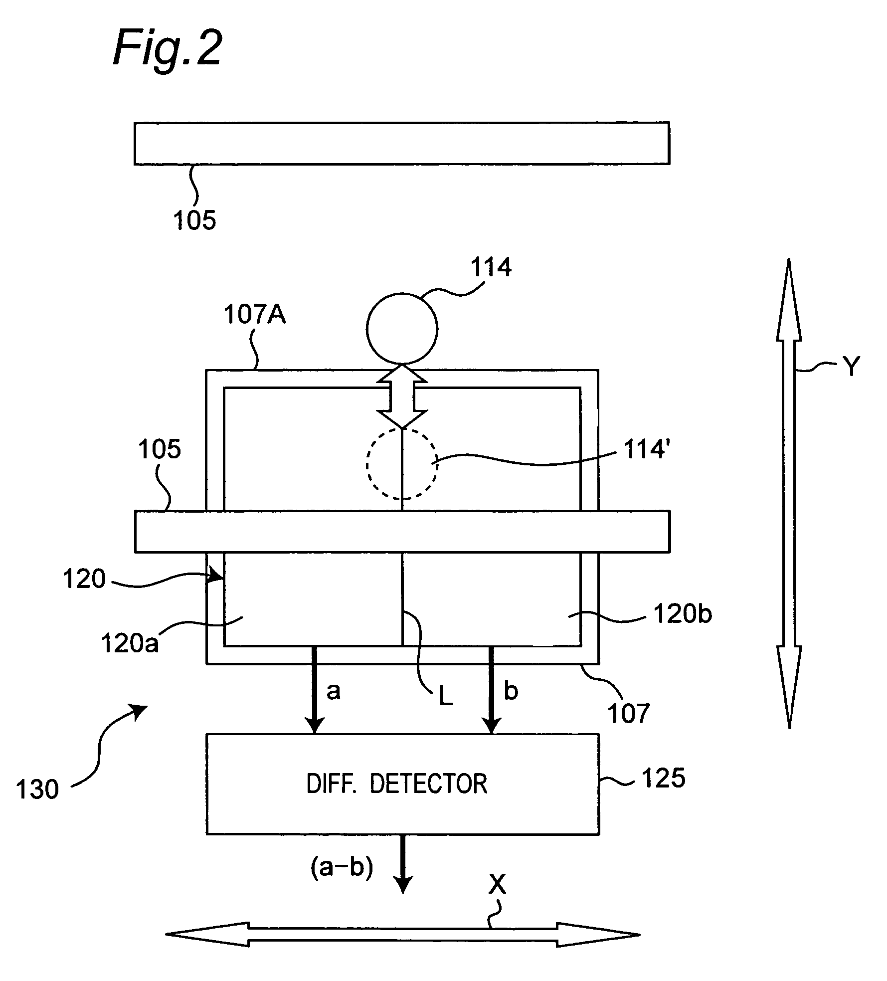
"The present invention aims to improve the accuracy of track pitch in information recording media by detecting and correcting variations in the position of the electron beam during recording. This is achieved by using a phenomenon where pits or patterns are recorded on a master using an electron beam, which causes the beam to bend and be shielded by a shielding plate. The position of the electron beam in a radial direction of the master is determined from a difference signal between two quantities of the electron beam irradiated on the shielding plate. This allows for highly accurate correction of positional variations of the electron beam. The electron beam recorder includes an electron optical system, a shielding plate, and an electron beam irradiation quantity detector with two detecting portions. By detecting the variations of the electron beam position while it is being irradiated on the master, the track pitch recorded on the master can be judged and corrected."

Problems solved by technology

However, this method is not applicable when signals are being recorded on the master 609.
Therefore, even in this method, it is extremely difficult to detect and correct the variations of the position of the electron beam 614 when the signals are being recorded on the master.

Method used


Image

  • Electron beam recorder, electron beam irradiation position detecting method and electron beam irradiation position controlling method
  • Electron beam recorder, electron beam irradiation position detecting method and electron beam irradiation position controlling method
  • Electron beam recorder, electron beam irradiation position detecting method and electron beam irradiation position controlling method

Examples


first embodiment

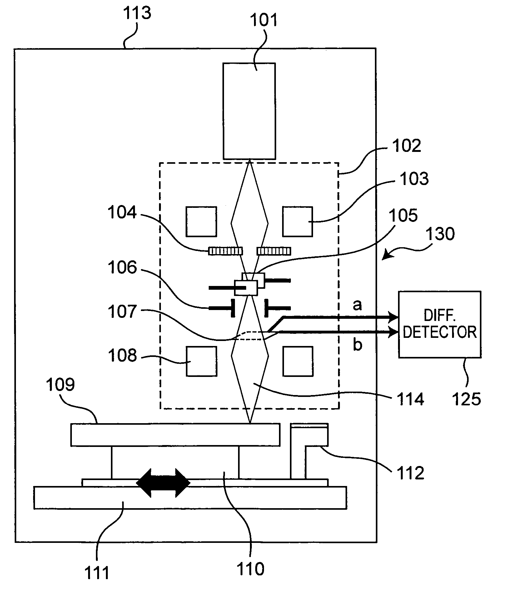
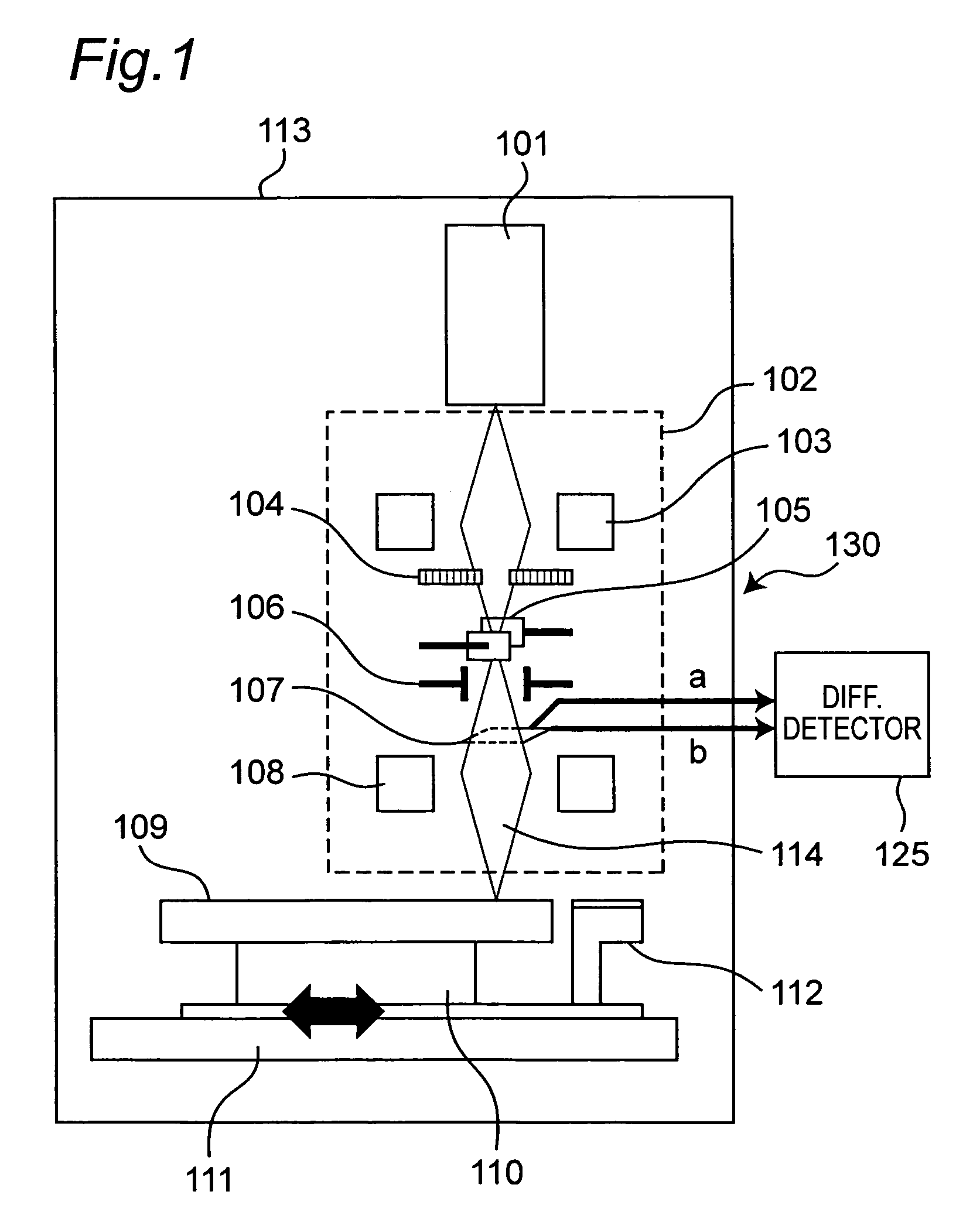
[0029]FIG. 1 shows an arrangement of an electron beam recorder for recording signals on a master 109 of an information recording medium, for example, an optical disc by using an electron beam 114, according to a first embodiment of the present invention. This electron beam recorder has a following structural portion similar to that of a conventional electron beam of FIG. 7. Namely, this electron beam recorder includes an electron beam source 101 for generating the electron beam 114 and an electron optical system 102 which converges the emitted electron beam 114 onto the resist master 109 so as to record information patterns on the resist master 109 in accordance with inputted information signals. The electron beam source 101 and the electron optical system 102 are accommodated in a vacuum chamber 113.

[0030]The electron beam source 101 is constituted by a filament for emitting electrons upon flow of electric current therethrough, an electrode for suppressing the emitted electrons, an...

second embodiment

[0046]FIG. 6 shows an arrangement of an electron beam recorder according to a second embodiment of the present invention. This electron beam recorder includes an electron beam irradiation position controller 150 connected between the difference detector 125 of the electron beam irradiation position detecting unit 130 and the second deflection electrodes 106. Since other constructions of the electron beam recorder are similar to those of the electron beam recorder of the first embodiment, the description is abbreviated for the sake of brevity.

[0047]In this arrangement of the electron beam recorder of FIG. 6, since variations of detected electron beam irradiation position are restrained by the electron beam irradiation position controller 150, nonuniformity of a track pitch of patterns recorded on the master 109 can be lessened. In case there is no variation of irradiation position, the difference detector 125 outputs, as the output signal (a−b), a zero signal corresponding to the ori...


PUM

PropertyMeasurementUnit
range frequencyaaaaaaaaaa
timeaaaaaaaaaa
diameteraaaaaaaaaa

Abstract

An electron beam recorder includes an electron optical system for irradiating the electron beam on a master of an information recording medium and a shielding plate for shielding the electron beam. An electron beam irradiation quantity detector is provided on the shielding plate and is divided into first and second electron beam detecting portions along an information recording direction on the master. A difference detector calculates a difference between a first quantity of the electron beam irradiated on the first electron beam detecting portion and a second quantity of the electron beam irradiated on the second electron beam detecting portion such that a position of the electron beam in a direction substantially perpendicular to the information recording direction is detected from the difference.

Description

BACKGROUND OF THE INVENTION[0001]1. Field of the Invention[0002]The present invention generally relates to electron beam recorders, electron beam irradiation position detecting methods and electron beam irradiation position controlling methods and more particularly, to an electron beam recorder, an electron beam irradiation detecting method and an electron beam irradiation position controlling method, in which signals are spirally recorded on a master of an information recording medium such as an optical disc highly accurately.[0003]2. Description of the Prior Art[0004]In general, manufacture of an optical disc includes a step in which by using an optical disc master recorder employing a laser or an electron beam as a light source, a master coated with photoresist is exposed and developed such that an optical disc master formed, on its surface, with concave and convex patterns such as information pits and grooves is produced, a step of producing a metallic die which has the concave ...

Claims


Application Information

Patent Timeline
Patent Type & Authority Patents(United States)
IPC IPC(8): G11B7/00G11B9/10H01J37/304
CPCH01J37/3045G11B7/261H01J2237/3045G11B9/10G11B11/03
Inventor TSUKUDA, MASAHIKOABE, SHINYA
Owner PANASONIC CORP
Learn More