Oscillator frequency control

a technology of oscillator frequency and control frequency, which is applied in the direction of frequency-modulated carrier system, digital transmission, resonance circuit details, etc., can solve the problems of phone connection with the base station, temperature compensation is less accurate than when used, and the frequency generated drift is not accurate, so as to achieve simple and cost-effective control

Inactive Publication Date: 2009-01-06
SONY ERICSSON MOBILE COMM AB
View PDF10 Cites 7 Cited by
  • Summary
  • Abstract
  • Description
  • Claims
  • Application Information

AI Technical Summary

Benefits of technology

[0009]The present Invention is therefore directed towards solving the problem of providing a simple and cost-efficent controlling of the frequency of a frequency source in a portable electronic device during temporary loss of communication with a reference frequency generator.
[0011]One object of the present invention is thus to provide a portable electronic device having simple and cost-effective Implementation for controlling the frequency of a frequency source included in the portable electronic device during temporary loss of communication with a reference frequency generator.
[0031]Another object of the present invention is directed towards providing a control device for a frequency source having simple and cost-effective implementation for controlling the frequency of the frequency source during temporary loss of communication with a reference frequency generator.
[0039]Another object of the present invention is to provide a method of controlling a frequency source that is simple and cost-effective to implement for controlling the frequency of the frequency source during temporary loss of communication with a reference frequency generator.
[0053]The present invention has many advantages. It is simple and easy to implement. It does not use any complicated or uncertain calculations of how the state of the device effects the frequency drift, like temperature, ageing and applied voltage. It fulfils the GSM requirements on limits of timing and frequency drift during a temporary loss of connection to a base station. It is cost-effective. Since it is based on controlling the frequency by the frequency from the reference frequency generator, which is already used in many portable electronic devices, it only requires small modifications of the device.

Problems solved by technology

It is well known that these oscillators are not exact in operation, but there is often a drift of the frequency generated because of among other things temperature variations and ageing of the oscillator.
Different parts of a phone can however have different temperatures, which results in that the temperature compensation is less accurate than when used in the static condition.
However, there is one problem with this adjustment and that is that the phone can lose connection with the base station.
This requirement can be hard to live up to if the drift is not compensated for also during loss of connection.
Temperature sensors add to the costs of a device and also occupy more space, both of which are important to keep down in the field of cellular phones.

Method used


Image

  • Oscillator frequency control
  • Oscillator frequency control
  • Oscillator frequency control

Examples


first embodiment

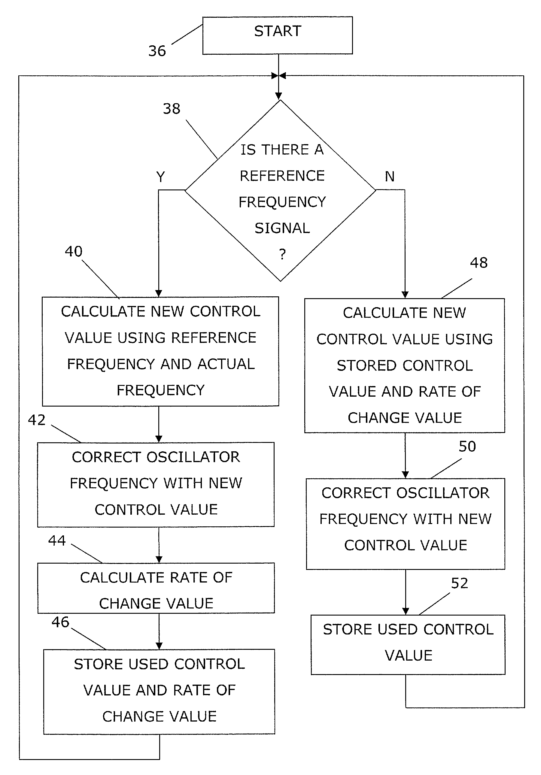
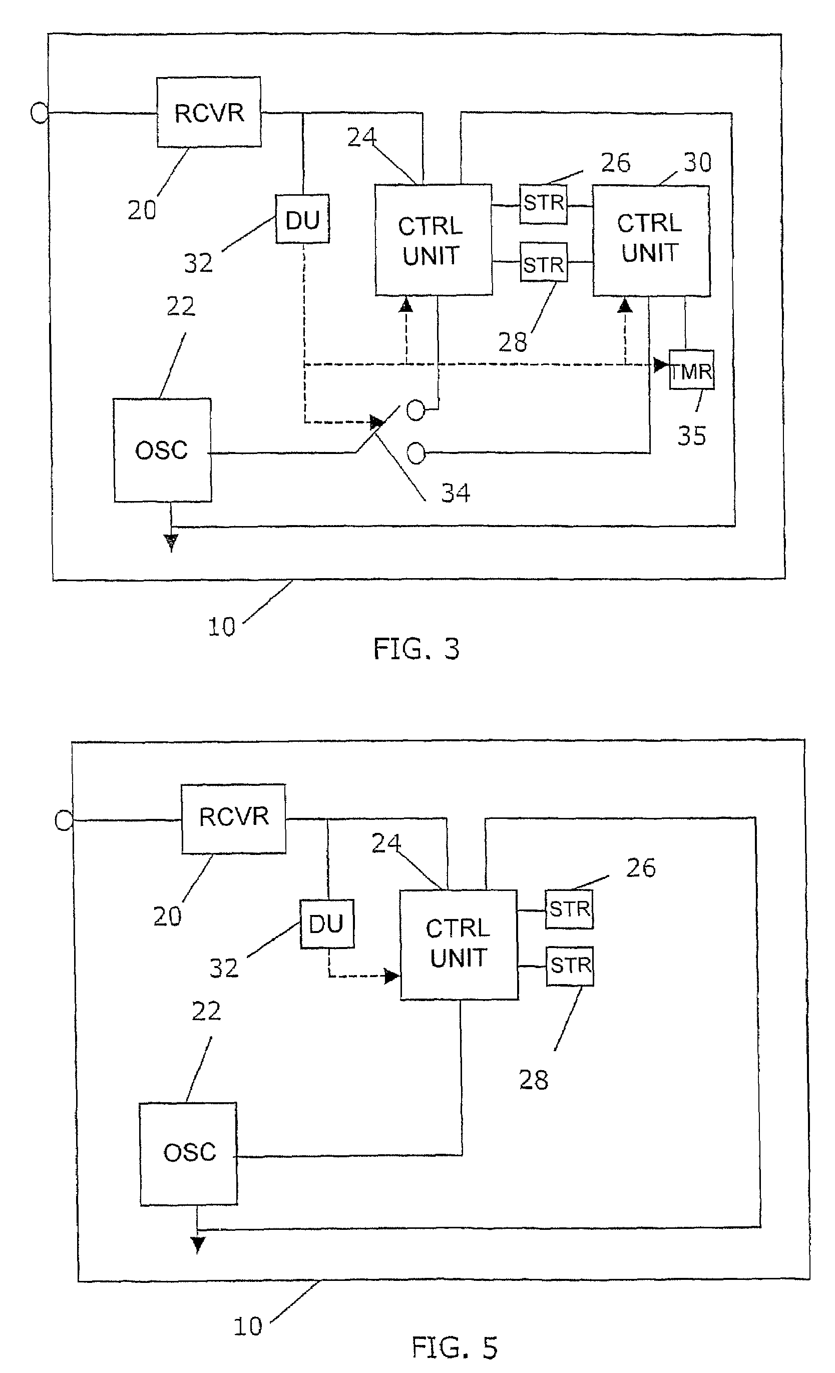
[0064]FIG. 3 shows a block schematic of the relevant parts of the phone 10 according to the present invention. The device includes a receiver 20 connected to the antenna (not shown). The receiver 20 is connected to a first control unit 24 as well as to a detecting unit 32. The first control unit 24 is connected to a control value store 26 and to a change of rate store 28. A second control unit 30 is also connected to the control value store 26 and to the change of rate store 28. The second control unit 30 is also connected to a timer 35. The detecting unit 32 controls a switch 34 via a control signal. The detection unit 32 also supplies the control signal to the first and the second control units 24 and 30 as well as to the timer 35. The supply of this control signal is indicated with dashed lines in the figure. The switch 34 is connected to a control input of the local frequency source 22, which in the preferred embodiment is a local frequency oscillator. The switch 34 is switchabl...

second embodiment

[0072]It is furthermore possible to vary the second embodiment even more. It is possible to include the detecting unit and the two stores in the sole control unit as well.

[0073]The control units are preferably provided in the form of a processor cooperating with program code stored in a program memory. The invention is therefore easy to implement in a phone by just adding some extra software, since some of it is already there. It also fulfils the requirements for limits on timing and frequency drift during loss of connection with a base station according to the GSM requirements. For these and other reasons the present Invention is only to be limited by the following claims.


PUM


Abstract

A control unit supplies a new control value to a frequency source. The value is determined by the frequency source frequency and the reference frequency. The control unit further calculates a rate of change value based at least on the new and a previous control value if there is communication with the reference frequency generator and stores these values in corresponding stores. Another control unit calculates a new control value based on the rate of change value from the rate of change store and the last used control value from the control value store and supplies the new control value to the frequency source if there is no communication with the reference generator.

Description

RELATED APPLICATIONS[0001]The present application is a 35 U.S.C. §371 national phase application of PCT International Application No. PCT / EP2003 / 013002, having an international filing date of Nov. 20, 2003, and claiming priority to European Patent Application No. 02025986.7, filed Nov. 21, 2002, and U.S. Provisional Application No. 60 / 429,141, filed Nov. 26, 2002, the disclosures of which are incorporated herein by reference in their entireties. The above PCT International Application was published in the English language and has International Publication No. WO 2004 / 047302 A1.TECHNICAL FIELD OF THE INVENTION[0002]The present invention generally relates to the field of portable electronic devices and more particularly to a method and devices for the control of the frequency of a frequency source.DESCRIPTION OF RELATED ART[0003]Cellular phones include local oscillators for generating frequencies. These frequencies are used for among other things clocking of circuits within the phone....

Claims


Application Information

Patent Timeline
Patent Type & Authority Patents(United States)
IPC IPC(8): H04L27/06H03J1/00H03J7/02H03L1/00H03L1/02H03L7/14
CPCH03J1/0041H03J7/026H03L1/00H03L1/02H03L7/14H04L27/12H03J2200/02H03J7/02
Inventor LINDELL, BOKRISTIANSSON, ROBERT
Owner SONY ERICSSON MOBILE COMM AB
Why Eureka
Try Eureka