Optical element such as multilayer film reflection mirror, production method therefor and device using it

Inactive Publication Date: 2009-01-06
NIKON CORP
View PDF25 Cites 27 Cited by
  • Summary
  • Abstract
  • Description
  • Claims
  • Application Information

AI Technical Summary

Benefits of technology

[0016]The formation of a correction film as well as the formation of a multilayer larger than necessary to substantially saturate the reflectance permits the correction of a phase by cutting away also the multilayer film when the phase cannot be corrected only by cutting away the correction film, whereby the phase can be corrected more accurately.
[0017]The use of the above-mentioned multilayer

Problems solved by technology

Since extreme ultraviolet rays and X-rays are not refracted in all materials because of the above reason, it is difficult to make a lens.
Accordingly, while reflectors are used to converge extreme ultraviolet rays and X-rays and to form images using them, even a metal surface does not always reflect extreme ultraviolet rays and X-rays.
However, since the metal surface can reflect extreme ultraviolet rays and X-rays when they are incident on it at an angle close to the metal surface, an optical system making use

Method used


Image

  • Optical element such as multilayer film reflection mirror, production method therefor and device using it
  • Optical element such as multilayer film reflection mirror, production method therefor and device using it
  • Optical element such as multilayer film reflection mirror, production method therefor and device using it

Examples


Example

BEST MODE OF CARRYING OUT THE INVENTION

[0029]Embodiments of the present invention will be described below in detail with reference to the drawings.

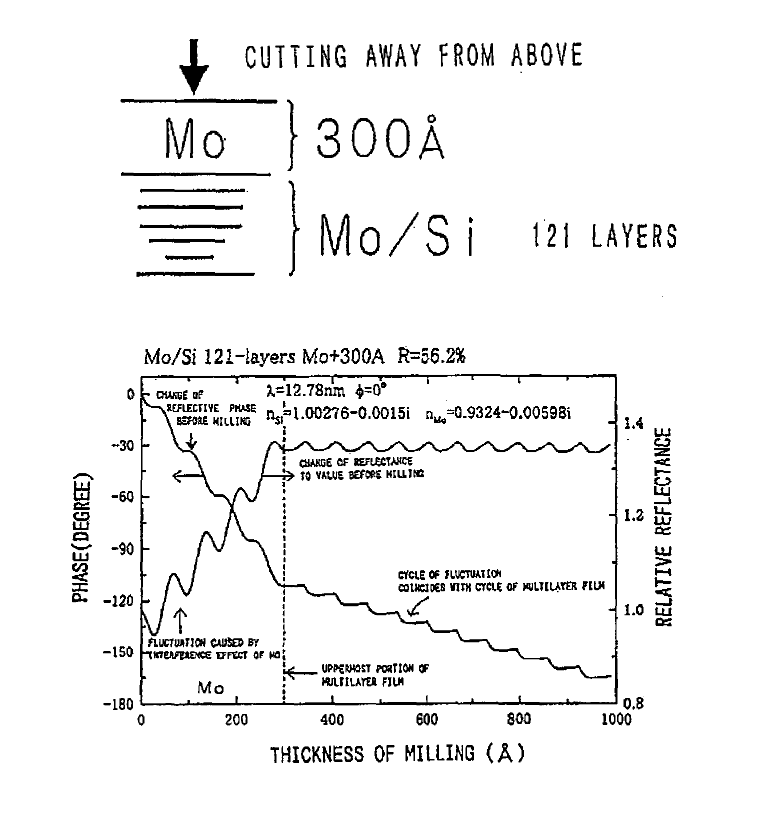
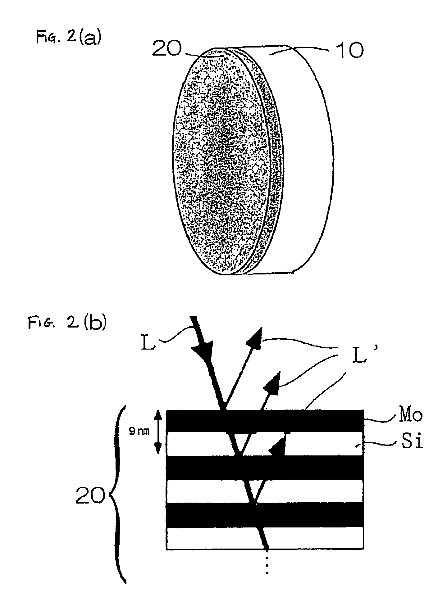
[0030]FIG. 5 is a graph showing a relationship between the number of cycles as the number of films of a multilayer films (number of repetitions of films constituting the reflective multilayer film, each of the films being composed of a material having a high refractive index and a material composed of a material having a low refractive index) and a reflectance in a reflector using a multilayer film as shown in FIG. 2(a). The films have an optical thickness of one fourth a wavelength, respectively. FIG. 5 shows a relationship between a multilayer film composed of ruthenium (Ru) and silicon (Si), a multilayer film composed of rhodium (Rh) and silicon (Si), a multilayer film composed of molybdenum (Mo) and silicon (Si), a multilayer film composed of ruthenium (Ru) and carbon (C), and a multilayer film composed of rhodium (Rh) and carbon (C) ...


PUM


Abstract

A multilayer film reflector capable of simply correcting a wavefront phase and a method of forming the reflector are disclosed.
For this purpose, a reflector using reflection by a multilayer film is disclosed. This multilayer film is formed in a number of cycles larger than that necessary to substantially saturate a reflectance, and a wavefront phase of emerging rays is adjusted by cutting away the multilayer film in accordance with an amount of adjustment of the wavefront phase.
Further, the formation of a correction film as well as the formation of a multilayer larger than necessary to substantially saturate the reflectance permits the correction of a phase by cutting away also the multilayer film when the phase cannot be corrected only by cutting away the correction film, whereby the phase can be corrected more accurately.

Description

TECHNICAL FIELD[0001]The present invention relates to an optical element such as a reflector, and the like making use of reflection by a multilayer film, and more particularly, to the correction of a wavefront phase of rays emerging from a multilayer film reflector.BACKGROUND ART[0002]FIG. 1 shows a relationship between the classification of electromagnetic waves and wavelengths thereof. First, extreme ultraviolet rays and X-rays will be described with reference to FIG. 1. Extreme ultraviolet rays (EUV) and vacuum ultraviolet rays (VUV) are electromagnetic waves having a wavelength shorter than that of ultraviolet rays in the classification of the electromagnetic waves shown in FIG. 1(a). As can be seen from the comparison of the classification of the electromagnetic waves of FIG. 1(a) with the wavelengths of electromagnetic waves of FIG. 1(b), X-rays indicate electromagnetic waves having a wavelength of 0.001 to 50 nm, wherein soft X-rays indicate X-rays having a wavelength of 0.5 ...

Claims


Application Information

Patent Timeline
IPC IPC(8): G21K1/06G03F7/20
CPCB82Y10/00G03F7/70316G21K1/062G21K2201/067G02B5/08G21K1/06
Inventor YAMAMOTO, MASAKI
Owner NIKON CORP
Why Eureka
Try Eureka