
Policing engine providing dynamic adjustment of peak and sustained data cell rates and efficient transfer of AAL5 cells

Active Publication Date: 2009-01-13
ADTRAN
View PDF7 Cites 2 Cited by
  • Summary
  • Abstract
  • Description
  • Claims
  • Application Information

AI Technical Summary

Benefits of technology

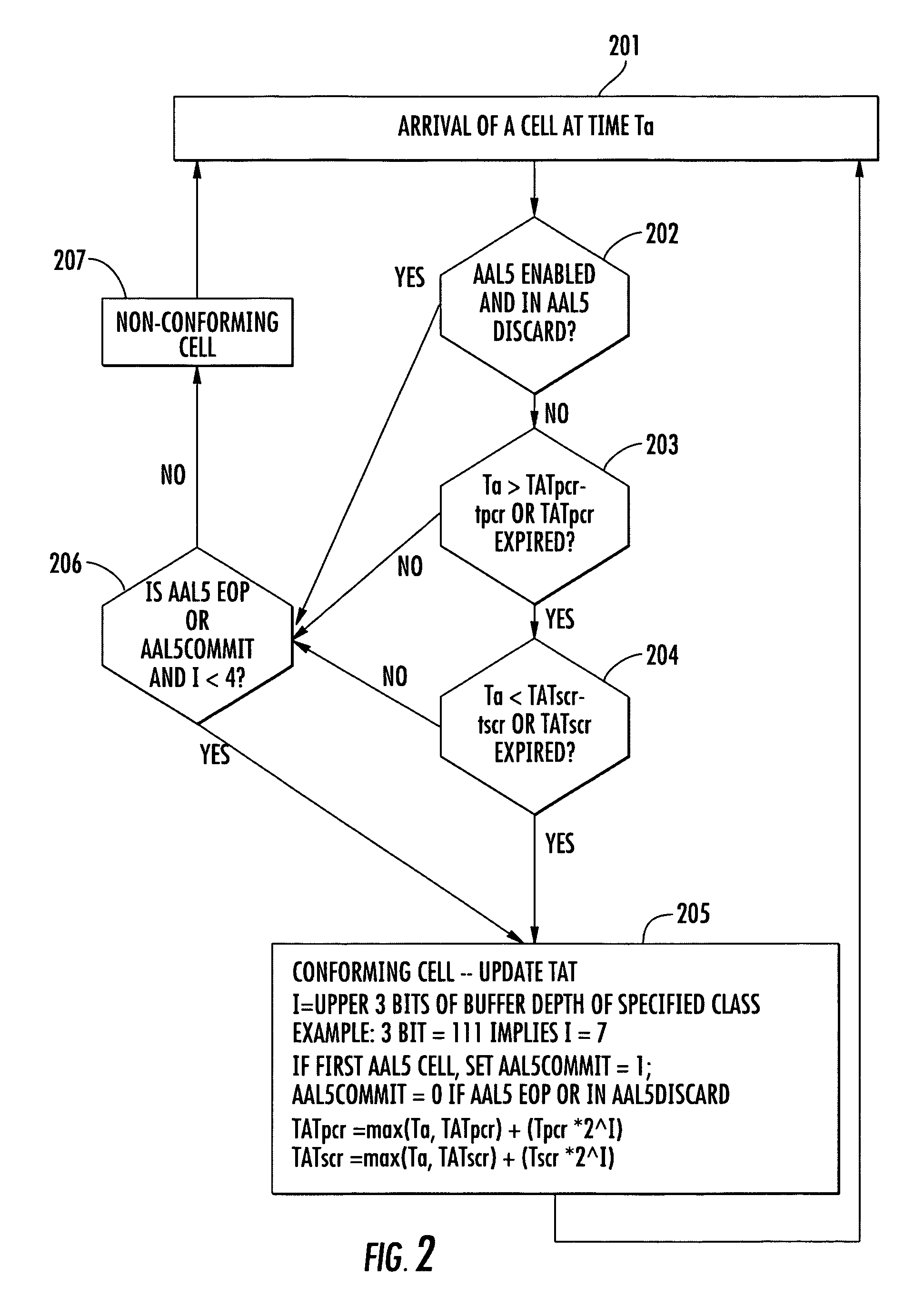
[0012]On the other hand, if the incoming packet is an AAL5 packet and the routine is not in AAL5 discard mode, the cell is processed to determine whether or not it is conforming. If the first cell of an AAL5 packet is determined to be conforming, and the buffer is not at least half full, which implies that it has sufficient capacity to store a complete AAL5 packet, the routine becomes ‘committed’ to accepting every AAL5 cell for storage in the buffer. On the other hand, if the policing engine has begun to discard AAL5 cells, it will continue to do so for all remaining cells of the AAL5 packet, except for an end of packet (EOP) cell. This avoids unnecessary processing of AAL5 cells, once it has been determined that the packet is to be discarded. If the first cell of the AAL5 frame has been accepted and the routine is committed to passing the entire AAL5 packet, then, as each AAL5 cell is received, it is used to update the peak and sustained cell rate theoretical arrival times. Once the last or EOP cell in the AAL5 packet is processed, the ‘commitment’ of the routine to automatically pass incoming cells is terminated, pending the arrival of a new packet.
[0016]The relationships for defining the theoretical arrival times are such that as a theoretical arrival time value is successively updated from an initial relatively small value, its value tends to increase substantially over several or more iterations. This has the effect of causing the police engine to discard cells supplied at elevated data rates, and tends to force the incoming cell traffic to conform with the sustained cell rate. The relationships also take into account how full the buffer has become. When the cell occupancy of the buffer is relatively small, the theoretical arrival time value is also smaller; however as the available storage depth of the buffer decreases, the theoretical arrival time value increases exponentially. This has the effect of significantly increasing the value of the theoretical arrival time value, so that a greater number of cells arriving at the policing engine will be discarded, rather than being buffered for transmission to the network. This ‘throttling’ of the incoming cells allows the cell occupancy of the buffer to be reduced as the cells are read out and forwarded to the switch fabric. Then, as the cell occupancy of the buffer decreases, the theoretical arrival time values decrease also, allowing more incoming cells to be accepted for storage in the buffer.

Problems solved by technology

The bus extension approach has a number of limitations.
For example, given the fact that the extension bus is shared among the master channel bank and one or more expansion channel banks, a problem may arise if one of the channel bank cards malfunctions and seizes control of the extension bus.
Moreover, since the channel banks are connected by way of a bus extension cable, there is a practical, noise-coupling limitation as to the number of channel banks that can be daisy chained together.
In addition, the bus extension cable is usually bulky and expensive.
The network card extension approach is also limited by a number of factors.
One is the fact that since the channel banks are interlinked by using network connections that usurp multiple line card slots, the primary bank loses the availability of line cards that would otherwise be used to provide service to customers.
Also, the use of network cards adds a greater expense for data expansion, and limits the number of customers that can be serviced by the host channel bank.
In addition, as each of the subtended channel banks requires a network connection, the switch fabric must be replicated on each subtended channel bank, which implies the need to replicate policing and scheduling mechanisms, and adds to the expense.

Method used


Image

  • Policing engine providing dynamic adjustment of peak and sustained data cell rates and efficient transfer of AAL5 cells
  • Policing engine providing dynamic adjustment of peak and sustained data cell rates and efficient transfer of AAL5 cells
  • Policing engine providing dynamic adjustment of peak and sustained data cell rates and efficient transfer of AAL5 cells

Examples


Embodiment Construction

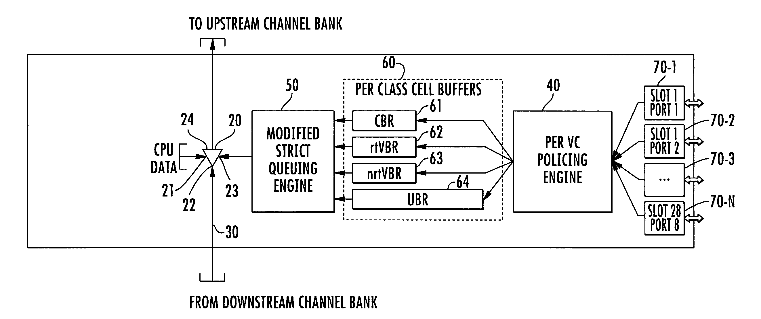
[0020]Before detailing the policing engine in accordance with the present invention, it should be observed that the invention resides primarily in a prescribed arrangement of conventional digital communication circuits and components and attendant supervisory communications microprocessor circuitry, as well as application software therefor, that controls the operations of such circuits and components. In a practical implementation that facilitates its incorporation into commercially available digital telecommunication transceiver equipment, the inventive arrangement is preferably implemented using field programmable gate array (FPGA)-configured, application specific integrated circuit (ASIC) chip sets. In a hardware implementation, digital ASICs are preferred.

[0021]Consequently, the configuration of such subsystems and components and the manner in which they may be interfaced with telecommunication channels have, for the most part, been shown in the drawings by a readily understanda...


PUM


Abstract

A policing engine for use in a telecommunication equipment shelf is operative to control the rate at which customer-sourced ATM packets are passed to buffers associated with different classes of service to which customers may subscribe. The policing engine examines the rate at which ATM cells are supplied to it from the line card ports, whether the cells are AAL5 cells, and how full are the buffers into which the cells are to be written. If cells are supplied to the policing engine at a rate faster than prescribed peak or sustained cell rates, or if the cell buffer begins to fill up, the policing engine controllably discards incoming cells, thereby effectively ‘throttling’ the cell flow rate through it.

Description

CROSS-REFERENCE TO RELATED APPLICATION[0001]The present application relates to subject matter disclosed in co-pending U.S. patent application Ser. No. 10 / 930,101 (hereinafter referred to as the '101 application), filed Aug. 31, 2004, entitled: “System Architecture for Linking Channel Banks of a Data Communication System,” by R. Burch et al, assigned to the assignee of the present application, and the disclosure of which is incorporated herein.FIELD OF THE INVENTION[0002]The present invention relates in general to telecommunication systems and subsystems thereof, and is particularly directed to a policing engine, respective ones of which are installable in channel banks of a multi-channel bank architecture of the type described in the '101 application, and which is operative to control the rate at which information cell packets supplied from customer ports of line card circuits of its channel bank are written into buffers associated with different classes of service to which customer...

Claims


Application Information

Patent Timeline
IPC IPC(8): H04J1/16
CPCH04L12/5601
Inventor BURCH, RICHARD A.JENSEN, NEIL M.MCMAHAN, DENNIS B.ROCHELL, TIMOTHY DAVID
Owner ADTRAN
Learn More