Bracket/spacer optimization in bladeless turbines, compressors and pumps

a bladeless turbine and compressor technology, applied in the direction of propellers, propulsive elements, water-acting propulsive elements, etc., can solve the problem that tesla cannot include such a component, and achieve the effect of reducing the ability of the disk to extract or infuse energy into or from the fluid system and reducing the kinematic viscosity

Inactive Publication Date: 2009-01-20
WILSON ERICH A
View PDF35 Cites 5 Cited by
  • Summary
  • Abstract
  • Description
  • Claims
  • Application Information

AI Technical Summary

Benefits of technology

[0011]A bladeless impeller, turbine, compressor or pump working with a compressible or incompressible fluid relies on the viscosity and impingement of the fluid to propel the disk assembly through the extraction or infusion of energy from the disk assembly to the fluid. Likewise, when energy is added into the working fluid from the disk assembly, it is through impingement and viscosity of the fluid the energy is transferred. Thus, as a working fluid with lower kinematic viscosity is implemented, the ability of the disks to extract or infuse energy into or from the fluid system is proportionally decreased whether this variational relationship be constant, linear or non-linear in nature.
[0016]An object of this invention is to improve disk / bracket assembly performance through implementing geometrical bracket / spacer variations with the arms deviating from a constant angular value in the centerline, median or mean.
[0017]An object of this invention is to improve disk / bracket assembly performance through implementing variation in the outermost diameter of the brackets and / or spacers independent of the geometry of the disk assembly.
[0018]A further object of this invention is to provide improved geometry to the flow chamber or chambers of the disk / bracket assembly through improving bracket / spacer design to maximize efficiency and improve performances through adhering geometry similar to a teardrop for the fluid flow chamber, thus maximizing the energy extraction or infusion to and / or from the working fluid.
[0019]Further, an object of the invention is to provide a variation in width of the bracket / spacer geometries which, based on the implementation of the bladeless turbine, compressor or disk, will maximize the efficiency of energy transfer within various performance parameters.
[0020]Further, an object of the invention is to delineate the leading and trailing edges of the bracket / spacer geometries which, based on the implementation of the bladeless turbine, compressor or disk, will maximize the efficiency of energy transfer within various performance parameters.

Problems solved by technology

Although, the bracket / spacer design disclosed here appears to be a fit for the disks in Tesla's patent, no effort is made by Tesla to include such a component.

Method used


Image

  • Bracket/spacer optimization in bladeless turbines, compressors and pumps
  • Bracket/spacer optimization in bladeless turbines, compressors and pumps
  • Bracket/spacer optimization in bladeless turbines, compressors and pumps

Examples


Embodiment Construction

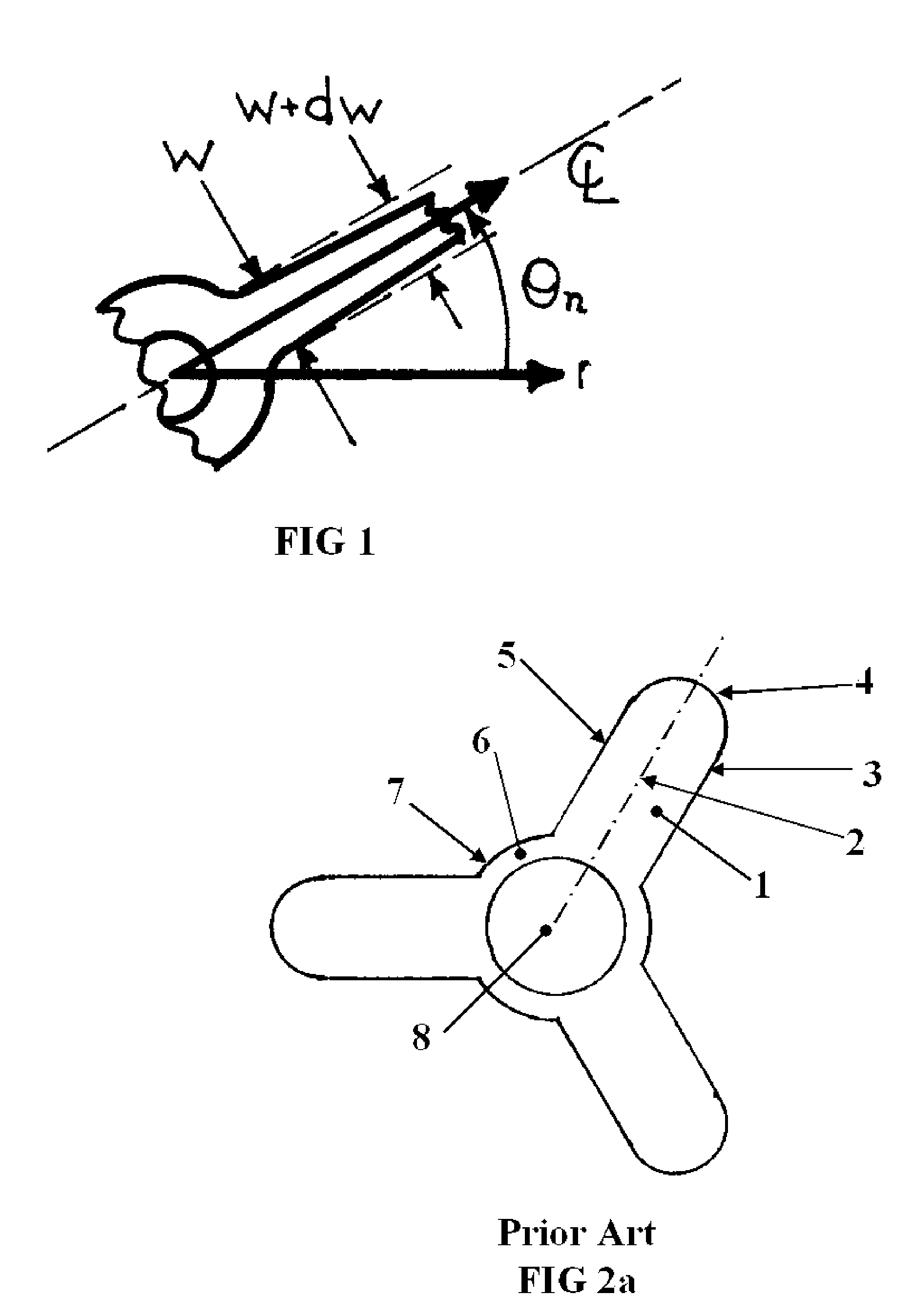
[0024]FIG. 1 denotes the variables necessary to explain the improvements provided in this invention as compared to prior art. The origin is placed at the center of rotation with the bracket or spacer extending radially outward in the r-direction and a nominal thickness in the x-direction coming out of the page. A distance, [θn], from the angular origin of an arm of the bracket or spacer is located by its centerline, [CL(r)], of constant angular direction for prior art and extending into the radial direction. Said arm is given a physical width, [w(r)], as a function of radial location as well as a decrease in width, [dw(r)], as it distances from the origin. Thus, the following definitions are given:

[0025]

Definition List 1TermDefinitiondFirst order differential for widthmAn integer denoting the number of armsnAn integer of value 1, 2, 3, . . . k − 1, krRadial directionRIDInner diameter of the bracket / spacer arm(s)RODOuter diameter of the bracket / spacer arm(s)wArm widthxAxial direction...


PUM


Abstract

A bracket / spacer design in a bladeless turbine, compressor or pump comprising of a hub for axial mounting and one or more arms connected to the hub. This bracket / spacer configuration contributes in part or completely to form one or more fluid flow chambers along with coinciding geometry of the neighboring disk or disks facilitating the entrance or exit of fluid for the purpose of extracting or infusing energy into or from the fluid. Furthermore, this invention includes a precise description of non-constant angular and axial geometry of the bracket / spacer arm or arms.

Description

FIELD OF THE INVENTION[0001]This invention relates to the improvement in geometric shape of an individual bracket / spacer used to build bladeless impellers, turbines, compressors, and pumps. This invention offers improvements in the bracket design to increase the efficiency of energy extraction or infusion between the working mechanical components and the working fluid of the system whether the fluid be compressible, incompressible, Newtonian or non-Newtonian in nature.BACKGROUND[0002]A bladeless turbine design was first patented by Nikola Tesla (U.S. Pat. No. 1,061,206) in 1913 for use as a steam turbine to extract energy from a working fluid. This original patent included the grouping of a series of disks and blades with identical passage holes symmetrically grouped around the rotational axis. The working fluid was introduced at a pressure and temperature through a form of nozzle at an angle on the outer perimeter of the disks. With only the passage holes in the disks as an outlet ...

Claims


Application Information

Patent Timeline
Patent Type & Authority Patents(United States)
IPC IPC(8): F01D1/36
CPCF01D1/36F05D2250/82F05D2250/84
Inventor WILSON, ERICH A.
Owner WILSON ERICH A
Why Eureka
Try Eureka