Combined storage basket

a combined and storage basket technology, applied in the direction of rigid containers, containers, packaging, etc., can solve the problems of high cost to fail economic benefits, waste of soldering time, and poor construction effect, and achieve the effect of saving shipping space and improving construction security

Inactive Publication Date: 2009-01-27
WIRE MASTER IND
View PDF9 Cites 10 Cited by
  • Summary
  • Abstract
  • Description
  • Claims
  • Application Information

AI Technical Summary

Benefits of technology

[0009]The primary purpose of the present invention is to provide a combined storage basket with all composite members knocked down ex-factory for saving shipping space and later to be assembled on site in a better secured construction.
[0010]Another purpose of the present invention is to provide a combined storage basket that allows upgraded quality for each composite member in a simplified manufacturing process by having prefabricated bolting holes and skirts to the frame of each panel to secure the basket with bolts.

Problems solved by technology

Conventional grid type storage basket usually comprised of multiple grid materials integrated with frames before being incorporated with a base panel though featuring simple construction and assembly consumes larger space either in ex-factory packaging, shipping and warehousing to result in comparatively higher costs to fail economic benefits.
The soldering process consumes too much time and the quality is questionable.
As a result, the grid panel can easily break away from its frame, particularly when subject to the impact of external force.
While causing additional labor and time costs, the locating member is vulnerable to dislocation due to absence of a corresponding positioning member.
Dislocated locating members prevent alignment with bolting holes to frustrate subsequent bolting process.
Accordingly, the basket is not firmly secured since the base panel is simply held by the front panel and the lower portion of the back panel; and the basket tends to shake and slacken, thus to significantly affect the firm construction of the basket, and endanger the safety and stability of the contents therein.

Method used


Image

  • Combined storage basket
  • Combined storage basket
  • Combined storage basket

Examples


Embodiment Construction

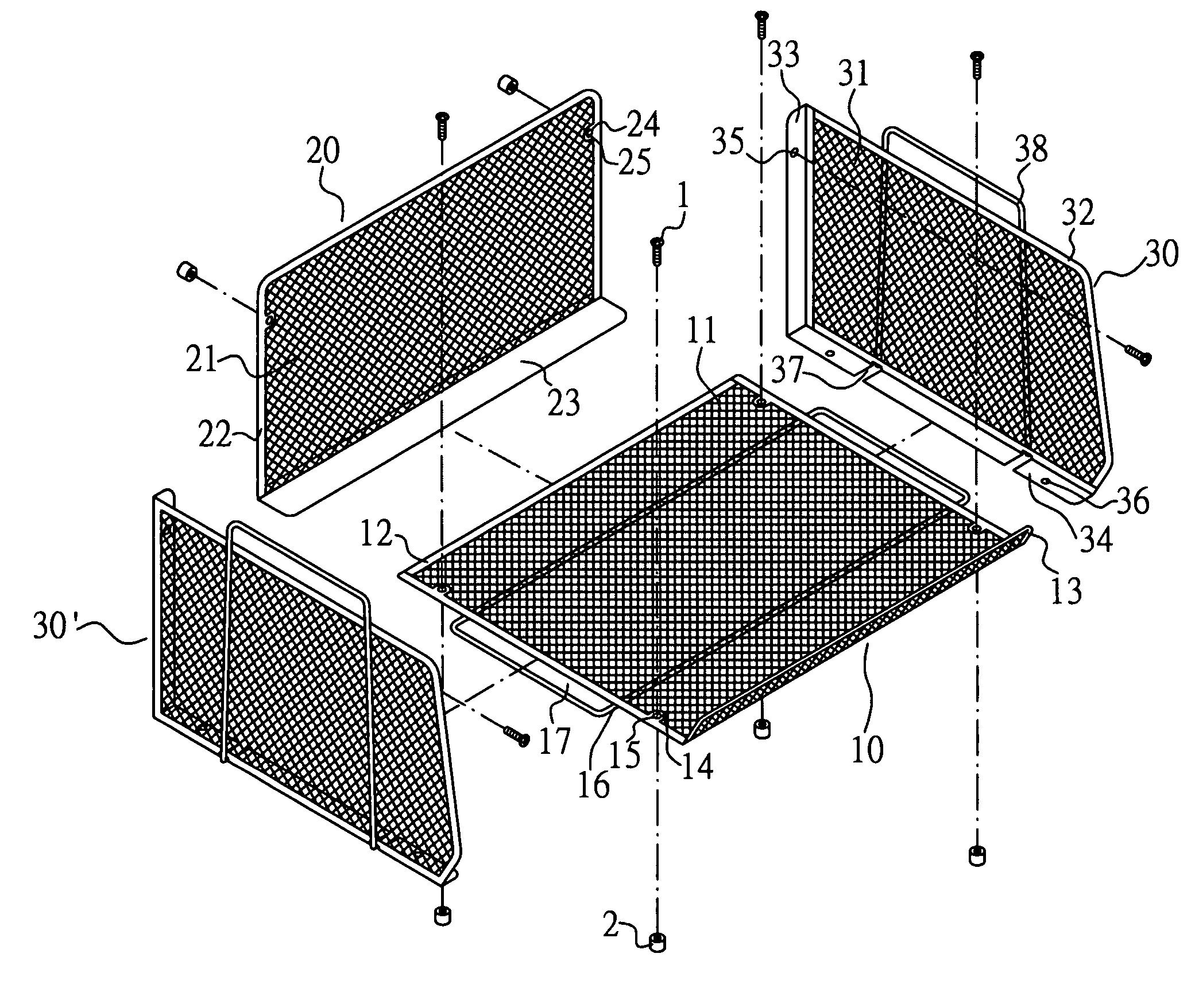
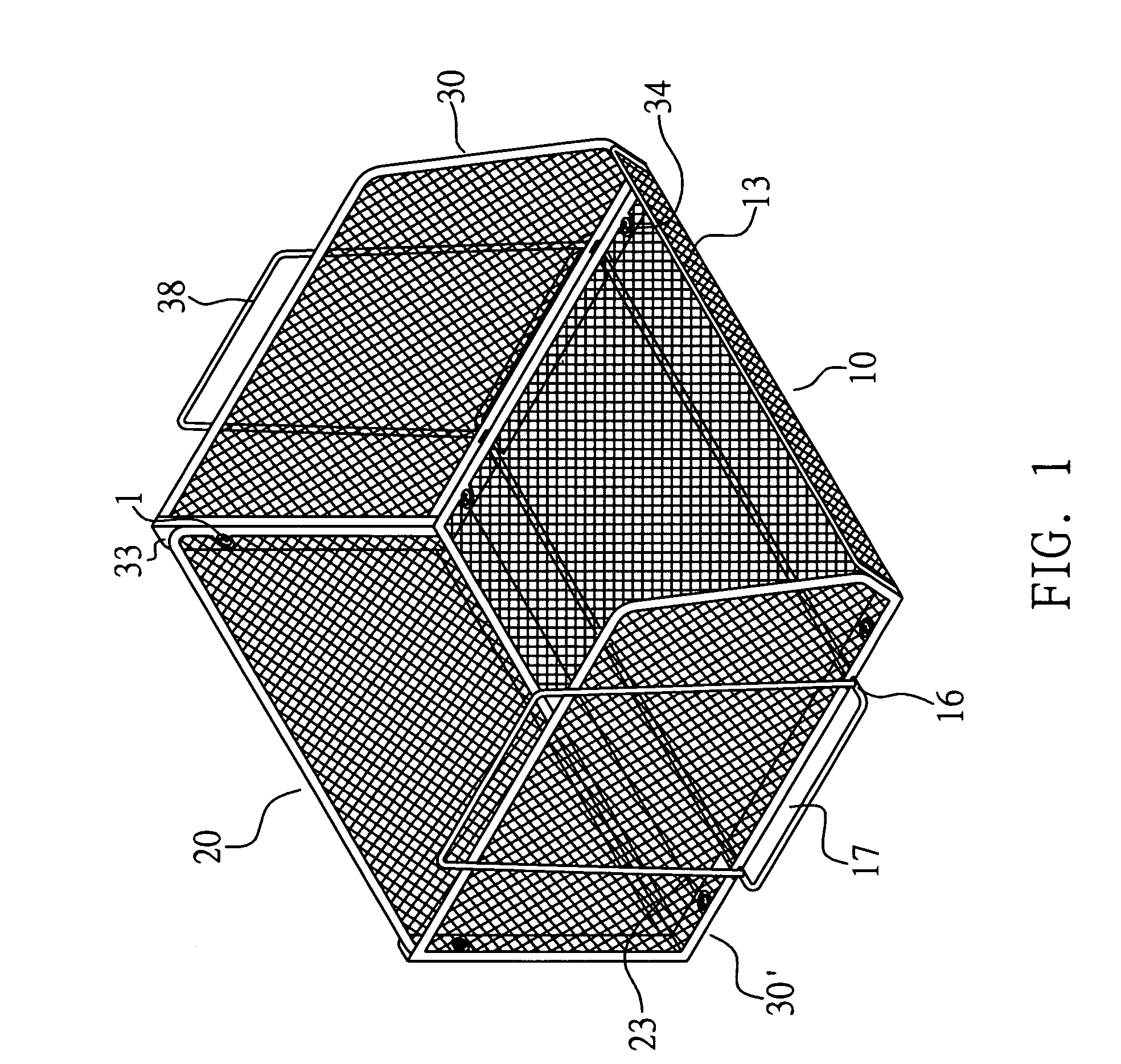
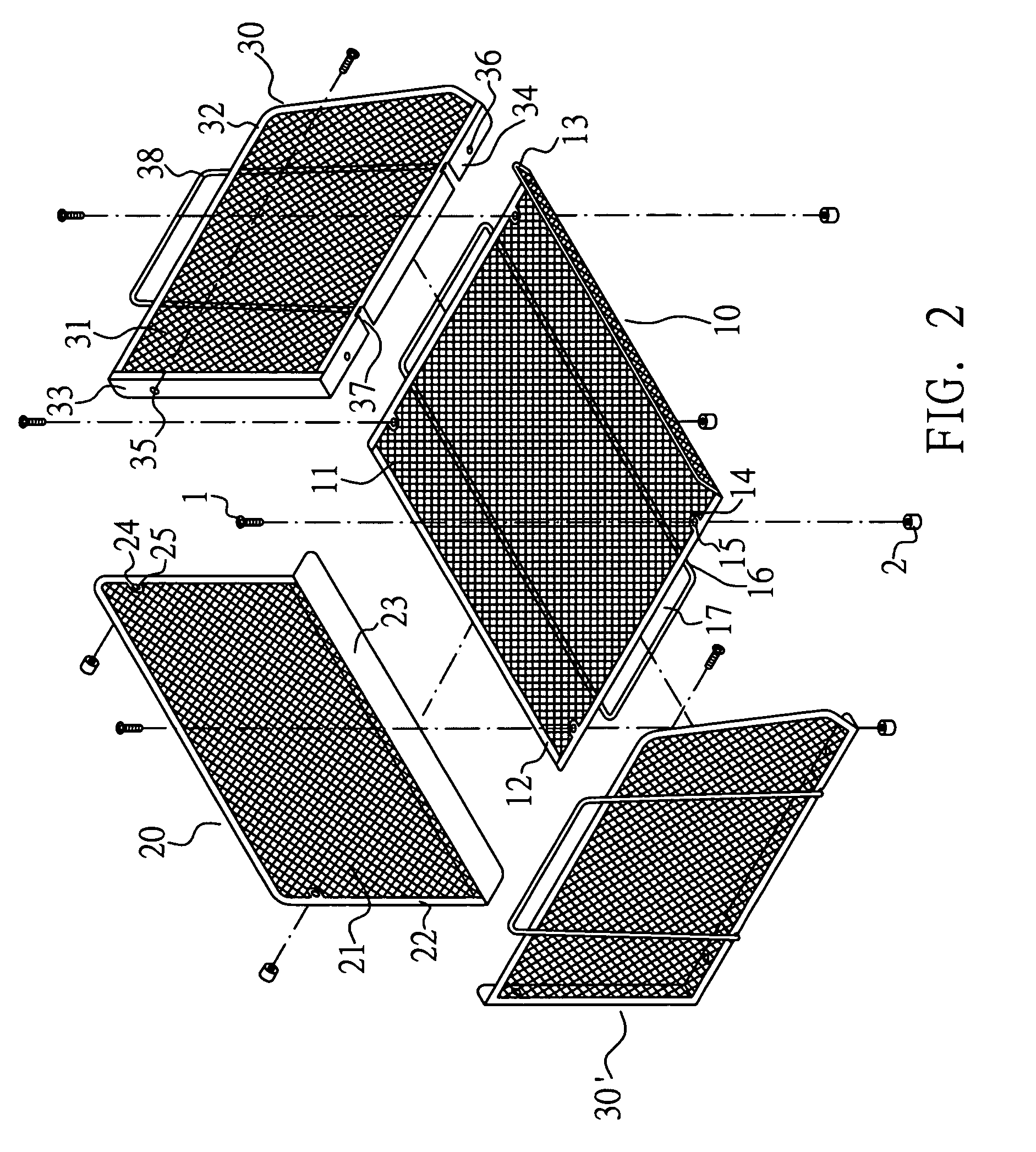
[0016]Referring to FIGS. 1, 2, and 3, a preferred embodiment of the present invention is essentially comprised of a base panel (10), a back panel (20) and two side panels (30, 30′) with multiple bolts (1) and rubber / plastic nuts (2).

[0017]Wherein, the base panel (10) includes a grid (11) molded in a preset specification and the peripheral of the grid (11) is soldered with a plate frame (12). The frame (12) covers up the peripheral of the grid (11) to prevent exposure of any end of the grid (11) and multiple (four in this preferred embodiment) connection members (13) each provided with a bolting hole (14) are provided on and integrated with both shorter sides of the base panel (10). An elevated retaining portion (15) in a proper width and is punched at the front edge of the base panel (10). A lateral frame (16) is provided beneath the base panel (10) and the width of the lateral frame (16) is slightly greater than that of the base panel (10) to reserve an insertion area (17) each on ...


PUM


Abstract

A combined storage basket allowing firm combination secured in position with bolts in prefabricated bolting holes for easy combination includes a base, a back, and two side grid panels; the basket has an open front; the base panel is placed on the bottom skirt of the back panel, the back panel slides into and is then bolted to inner side skirts of both side panels; and the back panel and the base panel are secured with bolts to both side panels; a rectangular frame in a width greater than that of the base panel is disposed beneath the base panel; and a vertical frame in Π shape is disposed to the back of each side panel with the top of vertical frame at a level higher than that of the top of the side panel to allow stacking up of multiple units of the basket.

Description

BACKGROUND OF THE INVENTION[0001](a) Field of the Invention[0002]The present invention is related to an improved construction of a combined storage basket, and more particularly, to a grid storage basket by having plate frame to replace rod frame for each composite panel of the prior art to provide better combination reliability of the frame and panel; and the combined basket is bolted in position with prefabricated skirts and bolting holes to each panel; the base panel is placed on the bottom skirts of the back panel first, then the back panel is secured to both side panels with rear skirts of both side panels; then and both side panels and is secured with bolts to the bottom skirts of both side panels.[0003](b) Description of the Prior Art[0004]Conventional grid type storage basket usually comprised of multiple grid materials integrated with frames before being incorporated with a base panel though featuring simple construction and assembly consumes larger space either in ex-facto...

Claims


Application Information

Patent Timeline
Patent Type & Authority Patents(United States)
IPC IPC(8): B65D6/24B65D90/08B65D21/032
CPCB65D7/16B65D7/24B65D21/0212
Inventor CHENG, HSI MING
Owner WIRE MASTER IND
Why Eureka
Try Eureka