Motor control device

a technology of motor control and control device, which is applied in the direction of motor/generator/converter stopper, electronic commutator, dynamo-electric converter control, etc., can solve the problems of increasing the cost of the entire system equipped with the motor, and the difficulty of detection of the phase current of two phases, so as to reduce the size of the minor axis

Active Publication Date: 2009-01-27
III HLDG 7
View PDF8 Cites 53 Cited by
  • Summary
  • Abstract
  • Description
  • Claims
  • Application Information

AI Technical Summary

Benefits of technology

[0019]In addition, for example, the superposing portion reduces the size of the minor axis of the ellipse in accordance with increase of the rotation speed or the drive voltage of the motor.

Problems solved by technology

Although two current sensors (current transformers or the like) are usually used for detecting the phase currents of two phases, the use of two current sensors causes an increase of cost of the entire system equipped with the motor.
However, if the maximum phase of voltage and an intermediate phase become close to each other, or if the minimum phase of voltage and the intermediate phase become close to each other, it is difficult to detect the phase currents of two phases.
It is possible to realize low cost and stable estimation at a standstill or the like by combining the single shunt current detecting method with the rotor position estimating method based on the application of a high frequency voltage, but a method for realizing the combination is not proposed yet.

Method used


Image

  • Motor control device
  • Motor control device
  • Motor control device

Examples


first example

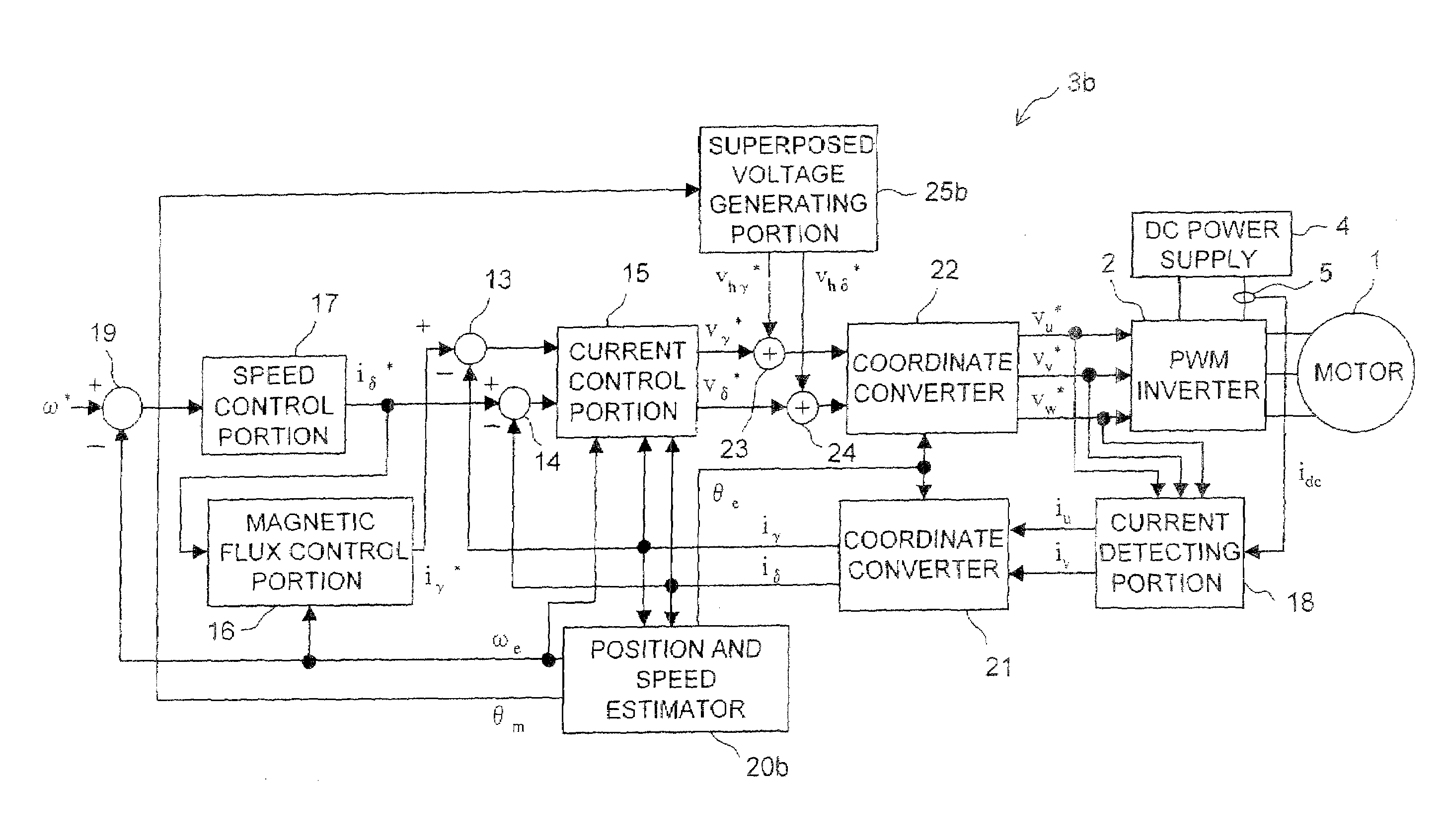
[0196]A first example will be described. FIG. 27 is a general structure block diagram of a motor driving system according to a first example. In FIG. 27, the same parts as those shown in FIG. 1 are denoted by the same reference numerals.

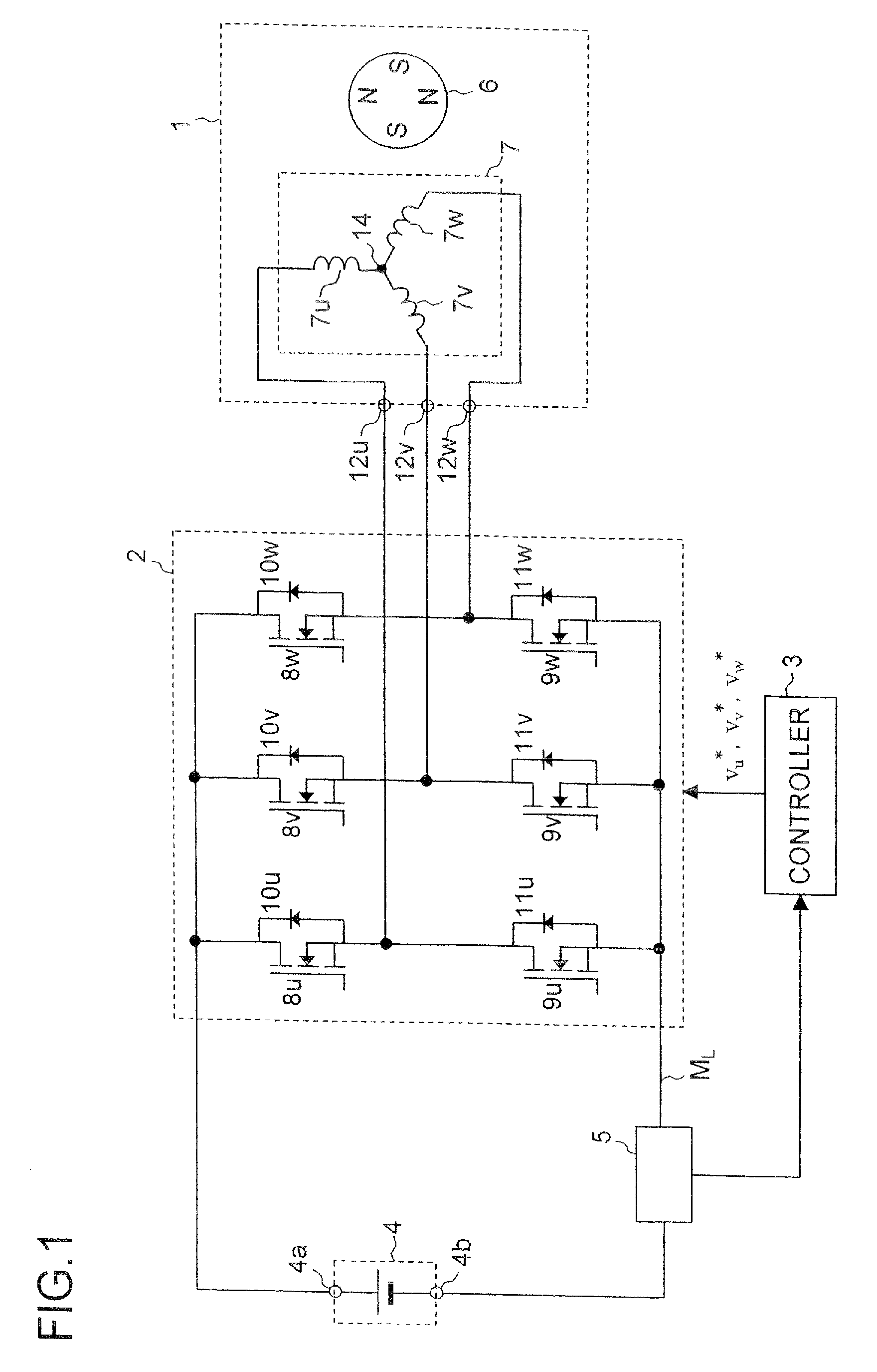
[0197]The motor driving system shown in FIG. 27 includes a motor 1, an inverter 2, a DC power supply 4 and a current sensor 5. It also includes a controller 3a that works as the controller 3 (the motor control device) shown in FIG. 1. The controller 3a includes subtracters 13 and 14, a current control portion 15, a magnetic flux control portion 16, a speed control portion 17, a current detecting portion 18, a subtracter 19, a position and speed estimator 20 (hereinafter referred to as “estimator 20” simply), coordinate converters 21 and 22, adders 23 and 24, and a superposed voltage generating portion 25.

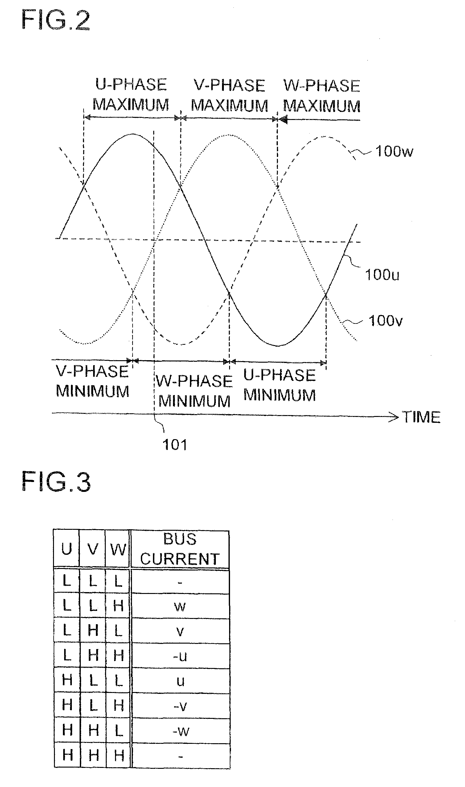
[0198]As described above, the current sensor 5 detects the bus current and delivers a signal indicating a current value of the bus current. The bus ...

second example

[0214]In addition, it is possible to use a coordinate converter 22a shown in FIG. 30 instead of the coordinate converter 22 shown in FIG. 29. While the coordinate converter 22 shown in FIG. 29 performs the voltage correction at the stage of the specified voltage vector of two phases, the coordinate converter 22a shown in FIG. 30 performs the voltage correction at the stage of the three-phase voltages, which leads to the same result as the voltage correction performed by the coordinate converter 22 shown in FIG. 29. As an example for describing the coordinate converter 22a, a second example will be described. A block diagram of a general structure of a motor driving system according to the second example is similar to that of the first example (see FIG. 27), so overlapping illustrations will be omitted. However, the coordinate converter 22a shown in FIG. 30 is used in the second example as the coordinate converter 22.

[0215]The coordinate converter 22a shown in FIG. 30 includes a coor...

third example

[0218]Next, a simulation result of evaluating estimation accuracy of the motor driving system according to the first or the second example will be described as a third example. In this simulation, a period for enabling detection of the phase currents of two phases is set to a value of approximately 5 microseconds, and the threshold value Δ indicating the maximum value of the b-axis component of the voltage correction quantity is set to 10 volts for securing the period. In other words, Δ is set to 10 volts so that the time periods T1-T2 and T2-T3 shown in FIG. 4 can be ensured to be approximately 5 microseconds or longer. In addition, the DC voltage supplied from the DC power supply 4 shown in FIG. 27 is set to 280 volts, and the amplitude (Vhγ) of the superposed voltage in the γ-axis direction is fixed to 40 volts.

[0219]FIGS. 31A and 31B and FIGS. 32A and 32B show the simulation result. In graphs shown in FIGS. 31A and 31B and FIGS. 32A and 32B, the horizontal axis represents time (...


PUM


Abstract

The motor control device includes a current detecting portion for detecting a phase current that flows in an armature winding of a stator of a three-phase motor based on current that flows between an inverter for driving the motor and a DC power supply. The motor control device performs a position sensorless vector control for the motor based on a control current that is obtained by a three-phase to two-phase conversion of the phase current based on an estimated rotor position of the motor. The motor control device farther includes a superposing portion for superposing a superposed voltage having a predetermined frequency on a drive voltage for driving the motor and an estimating portion for deriving the estimated rotor position based on the superposed current that is extracted from the control current and flows in the motor in accordance with the superposed voltage. A voltage vector locus of the superposed voltage from the superposing portion presents an ellipse.

Description

[0001]This nonprovisional application claims priority under 35 U.S.C. § 119(a) on Patent Application No. 2007-034607 filed in Japan on Feb. 15, 2007, the entire contents of which are hereby incorporated by reference.BACKGROUND OF THE INVENTION[0002]1. Field of the Invention[0003]The present invention relates to a motor control device for driving and controlling a motor.[0004]2. Description of Related Art[0005]In order to perform a vector control of a motor by supplying three-phase AC power to the motor, it is necessary to detect phase currents of two phases (e.g., the U-phase current and the V-phase current) among three phases including the U-phase, the V-phase and the W-phase. Although two current sensors (current transformers or the like) are usually used for detecting the phase currents of two phases, the use of two current sensors causes an increase of cost of the entire system equipped with the motor.[0006]For this reason, a conventional method is proposed, in which bus current...

Claims


Application Information

Patent Timeline
Patent Type & Authority Patents(United States)
IPC IPC(8): H02P23/00H02P6/16H02P6/06H02P6/08H02P6/17H02P6/28H02P21/00H02P21/14H02P21/18H02P21/22H02P21/24H02P21/28H02P23/14H02P23/16H02P27/04H02P27/08
CPCH02P6/18H02P21/0035H02P25/023H02P21/22H02P25/03
Inventor TOMIGASHI, YOSHIO
Owner III HLDG 7
Why Eureka
Try Eureka