
Forward error correction coding

a forward error correction and error correction technology, applied in the field of forward error correction (fec) coding, can solve the problems of increasing the requirements for optical and electrical components as well as transmission impairments, affecting the accuracy of coding, and the complexity of decoding should be as low as possible, so as to achieve the effect of increasing overhead

Inactive Publication Date: 2009-01-27
MARCONI COMM GMBH
View PDF1 Cites 15 Cited by
  • Summary
  • Abstract
  • Description
  • Claims
  • Application Information

AI Technical Summary

Benefits of technology

[0016]The present invention has arisen in an endeavour to provide FEC coding for use optical transmission systems that, at least in part, overcomes the limitations of the known coding schemes but without increasing the overhead.
[0020]Changing of the dimension of the binary outer codes and of the Reed-Solomon codes, especially to assimilate neighbouring outer codes, assists in reducing the number of stages for the multistage decoding procedure.
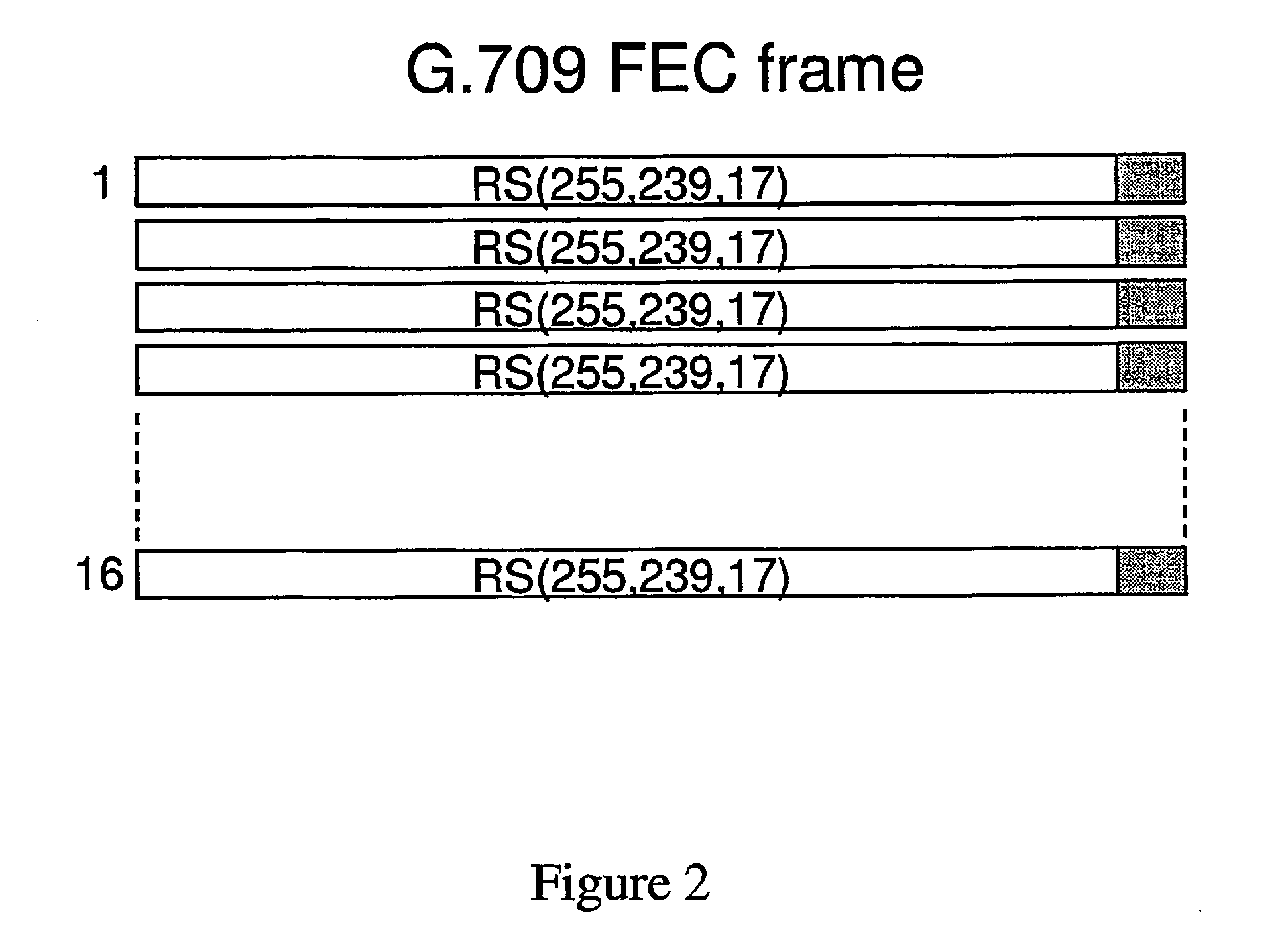
[0021]Preferably the code has a length (65280 bits) and rate, which is the same as that of 32 code words of the standard G.709 RS(255,239) code. Such a coding scheme enables it use in existing systems capable of operating with the standard FEC scheme. The coding scheme of the present invention can provide a higher coding gain (CG) without increasing the overhead rate of the code and hence line rate. At the same time the coding scheme avoids flaring effects through a high minimum Hamming distance of the concatenated code and the exploitation of this distance by means of algebraic multistage decoding.

Problems solved by technology

However, the rate of the code influences the bandwidth of the signal and therefore increases the requirements for optical and electrical components as well as transmission impairments that depend on the bandwidth.
Moreover, because of the high transmission rate the decoding complexity should be as low as possible.
In practice this low bit error rate cannot be verified with standard Monte Carlo simulations and is even difficult to measure.
The increased redundancy, however, is a disadvantage in current systems.
A problem with this type of coding scheme, compared to algebraic codes, is the small minimum Hamming distance that can lead to a behaviour for very low error rates that is similar to an error floor (the output bit error rate decreases very slowly with decreasing input bit error rate).
However, the actual behaviour at these low error rates is often difficult to predict
For this solution there is no error floor problem, but the complexity for decoding is also quite significant.
However, the construction of high (but not extremely high) rate codes requires matching all cyclotomic cosets (or unions of them) to nontrivial outer codes.

Method used


Image

  • Forward error correction coding
  • Forward error correction coding
  • Forward error correction coding

Examples


Embodiment Construction

[0032]As discussed concatenated codes were first proposed by Forney [D. Forney, Concatenated Codes, MIT Press, Cambridge, 1966]. Code concatenation allows long codes to be built from comparatively shorter component codes, and allows efficient decoding via the component codes. A generalised version of code concatenation (hereinafter termed GC codes) was introduced by Blokh and Zyablov [V. Blokh, V. Zyablov, “Coding of generalised concatenated codes,” Problems of Information Transmission, Volume 10 (1974), pp. 218-222]. In the following description of the coding scheme of the invention generalised concatenation is described as a sum of concatenated codes.

[0033]The addition of two code words of equal length, and over the same field, is done by adding the code vectors symbol by symbol The addition of two codes B1 and B2 is given as the addition of all possible pairs of code words with one code word from each code B1⊕B2={b1⊕b2|b1εB1, b2εB2}. If two linear codes have no common code word (...


PUM


Abstract

A forward error correcton coding method comprises a generalized concatenated code comprising a plurality of outer component codes and a plurality of inner component codes. The outer components codes comprise Reed-Solomon codes and a plurality of binary codes of equal length but varying rates. The inner component codes have a nested structure and are defined by the sum of disjoint Bose-Chaudhuri-Hocquenghem (BCH) codes. The inner and outer component codes are selected such that the product of the minimum Hamming distances of the inner and outer component codes are as equal as possible. Moreover, the component codes are selected by matching cyclotomic cosets of inner BCH codes and type and multiplicity of outer codes.

Description

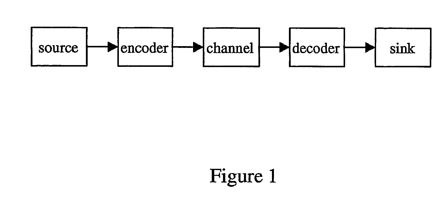
BACKGROUND OF THE INVENTION[0001]This invention relates to Forward Error Correction (FEC) coding and in particular FEC coding in optical communication systems.[0002]The objective of an optical communication system is to transmit (usually binary) communication data, error free, from a source to a destination in the form of optical radiation (optical channel) modulated with the communications traffic. However, there are many physical effects on the optical channel as it is transmitted from the source to the destination (such as for example random distortions like Amplified Spontaneous Emission ASE or thermal noise and deterministic distortions such as chromatic dispersion, Self Phase Modulation SPM, Cross Phase Modulation XPM, or Four Wave Mixing FWM) that can lead to transmission errors, that is a binary “0” at the input of the channel being received as a binary “1” and vice versa In order to improve the reliability of the channel, a technique known as channel coding is employed. FIG...

Claims


Application Information

Patent Timeline
IPC IPC(8): H03M13/00H03M13/29
CPCH03M13/2906
Inventor GRIESSER, HELMUTELBERS, JOERG-PETER
Owner MARCONI COMM GMBH
Learn More