Hole coring system

a coring system and hole technology, applied in the direction of drilling rods, drilling pipes, cutting machines, etc., can solve the problems of affecting the accuracy of drilling, so as to achieve the effect of high degree of control

Active Publication Date: 2009-02-03
U S SAWS
View PDF6 Cites 20 Cited by
  • Summary
  • Abstract
  • Description
  • Claims
  • Application Information

AI Technical Summary

Benefits of technology

[0013]According to the present invention a system has been devised that permits relatively large diameter holes to be drilled in a hard material like concrete, plastic, or fiberglass with a high degree of control in keeping the drill bit centered, but without the disadvantages of prior conventional systems. Specifically, according to the present invention a relatively small diameter pilot hole is first bored into the concrete at the precise center at which a larger diameter hole is to be drilled. Once the pilot hole has been drilled a mandrel is inserted into it and advanced into the hole. The lower end of the mandrel is advanced and then solidly anchored in the pilot hole. The remaining portion of the mandrel extends upwardly and serves as a stabilizing guidepost for a relatively large diameter, hollow drill bit drive shaft.
[0016]By utilizing the superior guidance provided by the mandrel and attached drill, high speed rotation can be achieved without vibration. This high speed enables the same or more power to be developed by the system with the lower pressure that can be applied by a manual operation.
[0017]By employing the stabilizing, anchored, mandrel and the hollow drive shaft assembly of the invention, the operator can precisely locate and drill a precision hole in a variety of materials using a hand operated portable tool.
[0021]To prevent such a dangerous situation the mandrel may be provided with a releaseable latching mechanism while the hollow, cylindrical, annular drive shaft is provided with an internal catch located below its driving end. As a result, the latching mechanism engages the internal catch once the driving end of the drive shaft is moved longitudinally relative to the anchoring support end of the mandrel and arrives at a predetermined engagement position relative thereto.

Problems solved by technology

One problem that has persisted, especially when relatively large-diameter holes are drilled into concrete using a cylindrical, annular core drill bit, is that it is sometimes difficult to maintain the drill bit precisely centered so as to drill a completely circular and aligned large diameter hole into concrete, fiberglass, plastic, and other materials.
The problem arises due to the tendency for one edge of the drill to make contact before another edge.
Consequently, the drill tries to walk sideways erratically.
There is a tendency for the drill bit to wobble or vibrate in a lateral direction, rather than stay precisely centered on the intended drill bit axis.
As a result, it is difficult to drill holes in concrete, particularly large diameter holes, with portable equipment.
However, unlike a drill press, there can be no stabilizing table beneath a workpiece when drilling into concrete.
This is because the concrete structure into which a hole is drilled is always much too thick and expansive to lend itself to stabilization by a table located beneath the drill.
If the drill supporting frame is not bolted or otherwise secured to the concrete floor, the drill bit tends to lift off the concrete surface being drilled.
Also, considerable effort is required to bolt the frame to the surface to be drilled.
However, it is difficult to achieve a sufficient suction force to prevent the frame from lifting off the floor and breaking the vacuum if one attempts to operate the drill with high torque.
Furthermore, conventional concrete core drills that employ stabilizing frames, such as the Core Drill Rig, are very bulky, heavy, and expensive.
They cannot be conveniently packed in a small carry case.
They also require a considerable volume of space for transportation in a truck or other work vehicle.
Although this drilling system has been around for many years it is unsatisfactory for many materials, including concrete.
This action is not practical for the larger diameter, thin walled core bit that a hand held drill motor can practically hammer and rotate.
Similarly a high rotational speed is more suited to the small pilot drill bit but these speeds may exceed the optimum speed for the large core bit, thus causing overheating and failure of the bit or melting of the material to be cut.
In addition, the pilot drill is not aligned in an orientation that can be checked for accuracy before commencing the drilling of the larger hole.
Also, the guiding tolerance does not remain constant since the pilot drill tends to “oval” the pilot hole with continued rotation thus causing irregular holes, variable location and misalignment.

Method used


Image

  • Hole coring system
  • Hole coring system
  • Hole coring system

Examples


Embodiment Construction

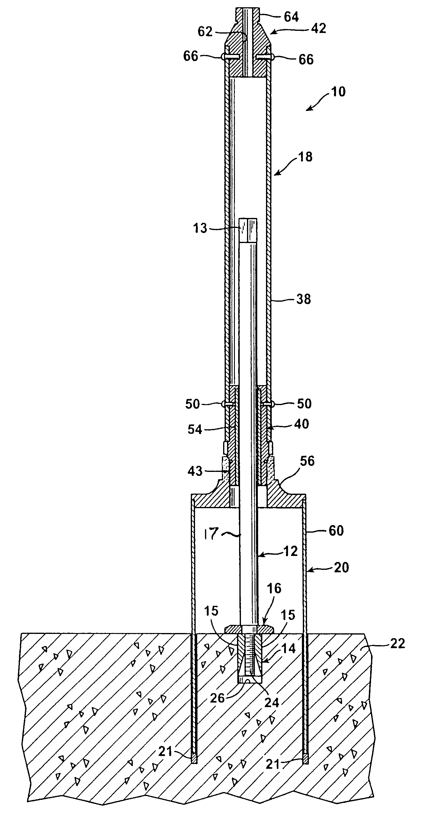
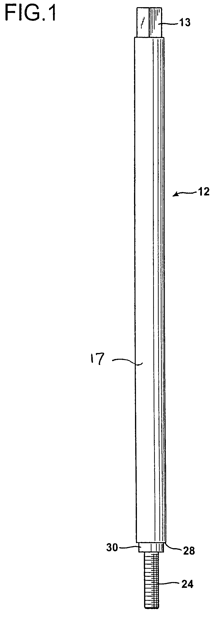
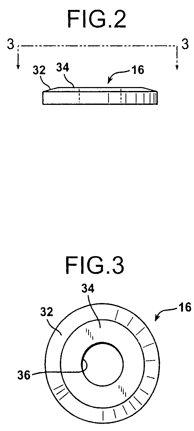
[0046]FIG. 10 illustrates a hole coring system 10 according to the invention. The hole coring system 10 includes a mandrel 12, an anchor mechanism 14 attached to the lower end of the mandrel 12, a shoulder washer 16 for stabilizing the mandrel 12, a drive shaft assembly 18, and a hollow, tubular core drill bit 20. The mandrel 12 is a long, solid steel rod having an upper engagement end 13 of hexagonal cross section and an externally threaded lower anchoring support end 24. The mandrel 12 has a smooth, cylindrical, intermediate, outer surface 17 between its upper end 13 and its lower end 24. The diameter of the lower mandrel end 24 is smaller than the diameter of the cylindrical outer surface 17. The mandrel 12 is shown in isolation in FIG. 1.

[0047]As shown in FIG. 4 the lower, anchoring support end 24 is provided with an expansion anchor mechanism 14. The anchor mechanism 14 is an expansion anchor that provides a rigid connection between the concrete material to be drilled, indicate...


PUM


Abstract

An apparatus for drilling holes in a substrate wherein a mandrel is anchored to the substrate. A hollow drill bit rotates about the mandrel via a drive motor and is a guided along a length of the mandrel.

Description

[0001]The present application claims the benefit of Provisional Patent Application Ser. No. 60 / 759,594 filed Jan. 17, 2006.BACKGROUND OF THE INVENTION[0002]1. Field of the Invention[0003]The present invention relates to a tool designed to drill holes in concrete and other materials.[0004]2. Description of the Prior Art[0005]Holes have been drilled in concrete using masonry drill bits for many years. One problem that has persisted, especially when relatively large-diameter holes are drilled into concrete using a cylindrical, annular core drill bit, is that it is sometimes difficult to maintain the drill bit precisely centered so as to drill a completely circular and aligned large diameter hole into concrete, fiberglass, plastic, and other materials. The problem arises due to the tendency for one edge of the drill to make contact before another edge. Consequently, the drill tries to walk sideways erratically. There is a tendency for the drill bit to wobble or vibrate in a lateral dire...

Claims


Application Information

Patent Timeline
Patent Type & Authority Patents(United States)
IPC IPC(8): E21B10/02
CPCE21B10/02E21B19/24
Inventor DUNCAN
Owner U S SAWS
Why Eureka
Try Eureka