Brinelling bushing joint assembly

a technology of bushings and joints, applied in the field of joint assemblies, can solve the problems of reducing the assembly efficiency of the joint assembly, reducing the assembly efficiency of the joint, and reducing the assembly time of the joint, so as to reduce the number of parts used, reduce the assembly time, and withstand higher loading

Inactive Publication Date: 2009-02-03
GM GLOBAL TECH OPERATIONS LLC
View PDF7 Cites 9 Cited by
  • Summary
  • Abstract
  • Description
  • Claims
  • Application Information

AI Technical Summary

Benefits of technology

[0007]An advantage of an embodiment of the present invention is that the brinelling bushing joint assembly may be able to withstand higher loading due to the mechanical lock between the brinelling bushing sleeve and the bracket, while minimizing the number of parts used in the joint. This also minimizes the assembly time for the joint, which may reduce the overall cost.
[0008]An advantage of an embodiment of the present invention is that the joint efficiency created by the mechanical lock between the brinelling bushing sleeve and the bracket may allow, for particular vehicle applications, a reduced fastener sizing. This reduction may result in a reduced fastener and component part mass and cost, and a reduced fastener joint size for improved packaging efficiency.
[0009]An advantage of an embodiment of the present invention is that the brinelling bushing joint assembly may reassemble relatively easily even though the brinelling feature may cause some displacement of bracket material by the brinelling features on the brinelling bushing sleeve.

Problems solved by technology

But this adds extra parts to an assembly and extra steps to the process of assembling these joints.
But the serrations are somewhat destructive to the bracket, making re-assembly of a joint assembly more difficult than is desired.

Method used


Image

  • Brinelling bushing joint assembly
  • Brinelling bushing joint assembly
  • Brinelling bushing joint assembly

Examples


Embodiment Construction

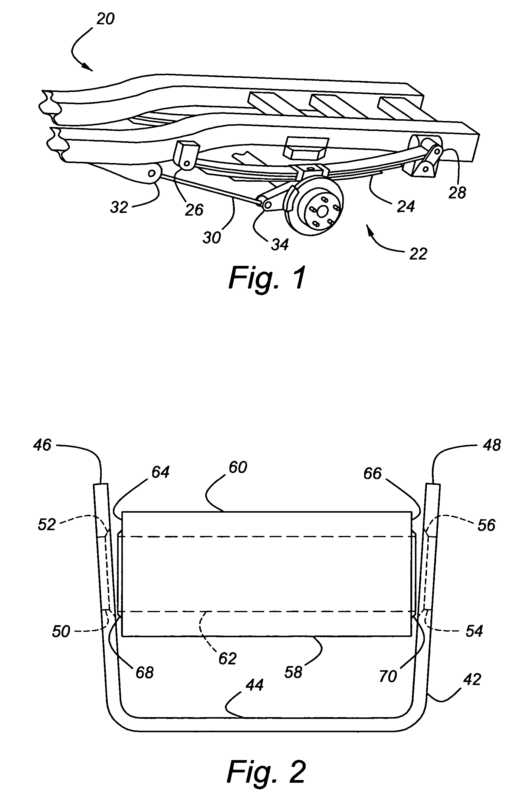
[0017]FIG. 1 illustrates a vehicle frame, indicated generally at 20, having a vehicle suspension, indicated generally at 22, mounted thereto. When using the term vehicle frame herein, this term also includes structure such as a sub-frame or an integral body frame. The vehicle suspension 22 has a leaf spring 24, with a front joint assembly 26 and a rear joint assembly 28. The vehicle suspension 22 also has an anti-windup link 30, with a front joint assembly 32 and a rear joint assembly 34. The front and rear joint assemblies 26, 28 for the spring 24 and the front and rear joint assemblies 32, 34 for the anti-windup link 30 are examples of vehicle locations where a brinelling bushing joint assembly 36 (illustrated in detail in FIGS. 2-7) may be used. Of course, the joint assembly of the present invention can also be used in other applications where the capability to handle high joint loads is desired.

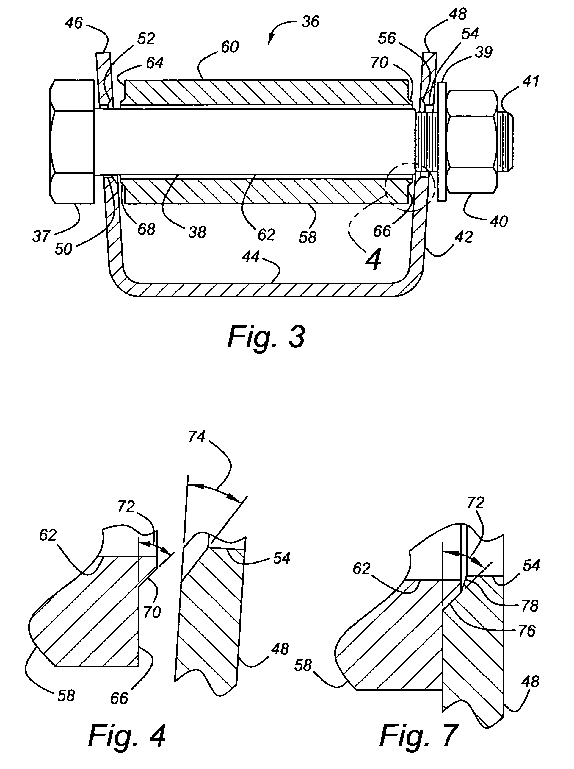
[0018]FIGS. 2-4 illustrate the brinelling bushing joint assembly 36 prior to a fasten...


PUM


Abstract

The invention concerns a brinelling bushing joint assembly having a brinelling bushing sleeve with a brinelling feature that mates with a bracket. This joint assembly may be particularly advantageous when employed to connect a vehicle frame to a vehicle suspension.

Description

BACKGROUND OF INVENTION[0001]The present invention relates generally to a joint assembly, and in particular to a joint assembly that may be employed in a vehicle suspension.[0002]Bushings are often used in joint assemblies where one component must be able to pivot relative to the other. Such assemblies may include a bolt that extends through the bushing and a bracket attached to a first component, with a second component mounted about the bushing. For example, some locations where components of a vehicle suspension mount to components of a vehicle frame may include such joint assemblies.[0003]Often, these joint assemblies, and so the fasteners within them, must withstand high loading. Some have employed separate brinelling (conical) washers between bushing sleeves and brackets to help withstand the high loading. But this adds extra parts to an assembly and extra steps to the process of assembling these joints. Others have added serrations machined into the ends of a bushing sleeve t...

Claims


Application Information

Patent Timeline
Patent Type & Authority Patents(United States)
IPC IPC(8): B60G9/02B60G11/12F16C33/04
CPCB60G7/02B60G11/12B60G2204/121Y10T403/32861B60G2204/41B60G2204/43B60G2204/44B60G2204/143
Inventor SOLES, PETER J.MONAGHAN, JOHN T.OLSON, KEITH E.
Owner GM GLOBAL TECH OPERATIONS LLC
Why Eureka
Try Eureka