Vertical boat for heat treatment and method for producing the same

a technology of heat treatment and vertical boat, which is applied in the direction of lighting and heating apparatus, muffle furnaces, furnaces, etc., can solve the problems of low production cost and low cost of boats, and achieve the effects of low material cost, low production cost and easy production

Active Publication Date: 2009-02-03
SHIN-ETSU HANDOTAI CO LTD
View PDF15 Cites 43 Cited by
  • Summary
  • Abstract
  • Description
  • Claims
  • Application Information

AI Technical Summary

Benefits of technology

[0019]In view of such problems as described above, an object of the present invention is to provide a vertical boat for heat treatment that can effectively prevent a slip from being generated in a wafer and such during heat treatment, has low material cost, and can be relatively easily produced.

Problems solved by technology

Therefore, production yield is high, production cost becomes low, and consequently the boat becomes low in cost.

Method used


Image

  • Vertical boat for heat treatment and method for producing the same
  • Vertical boat for heat treatment and method for producing the same
  • Vertical boat for heat treatment and method for producing the same

Examples


example 1

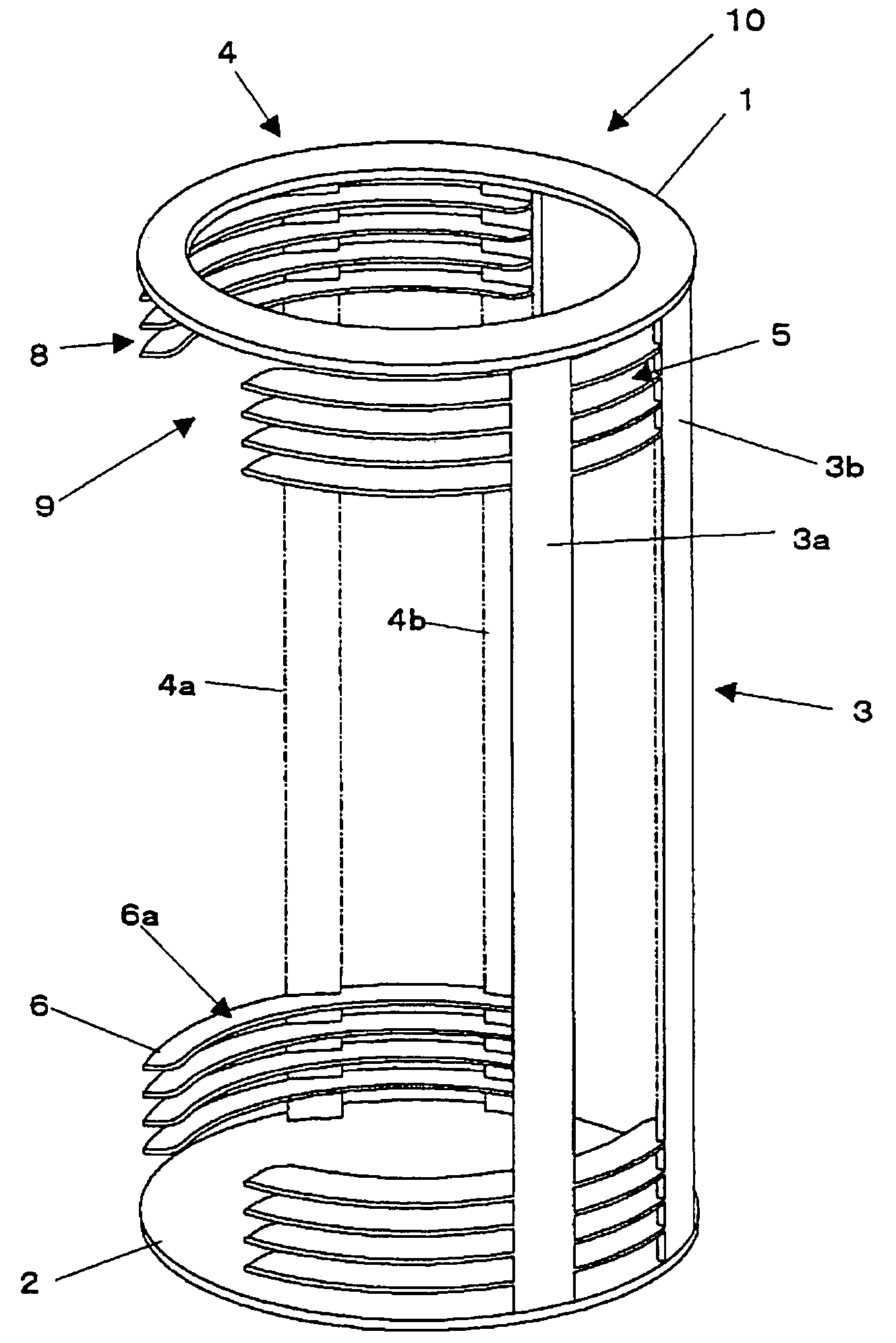
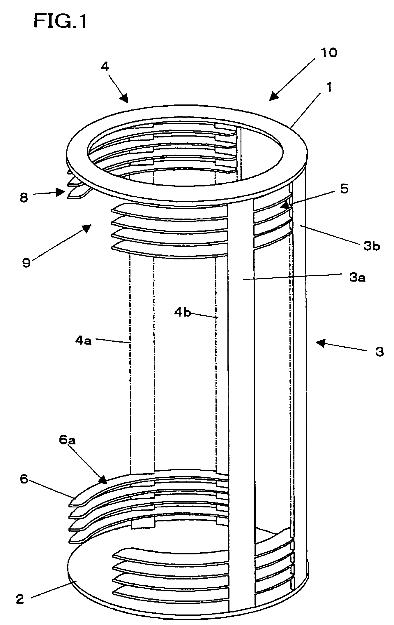
[0086]Production of the Vertical Boat for Heat Treatment

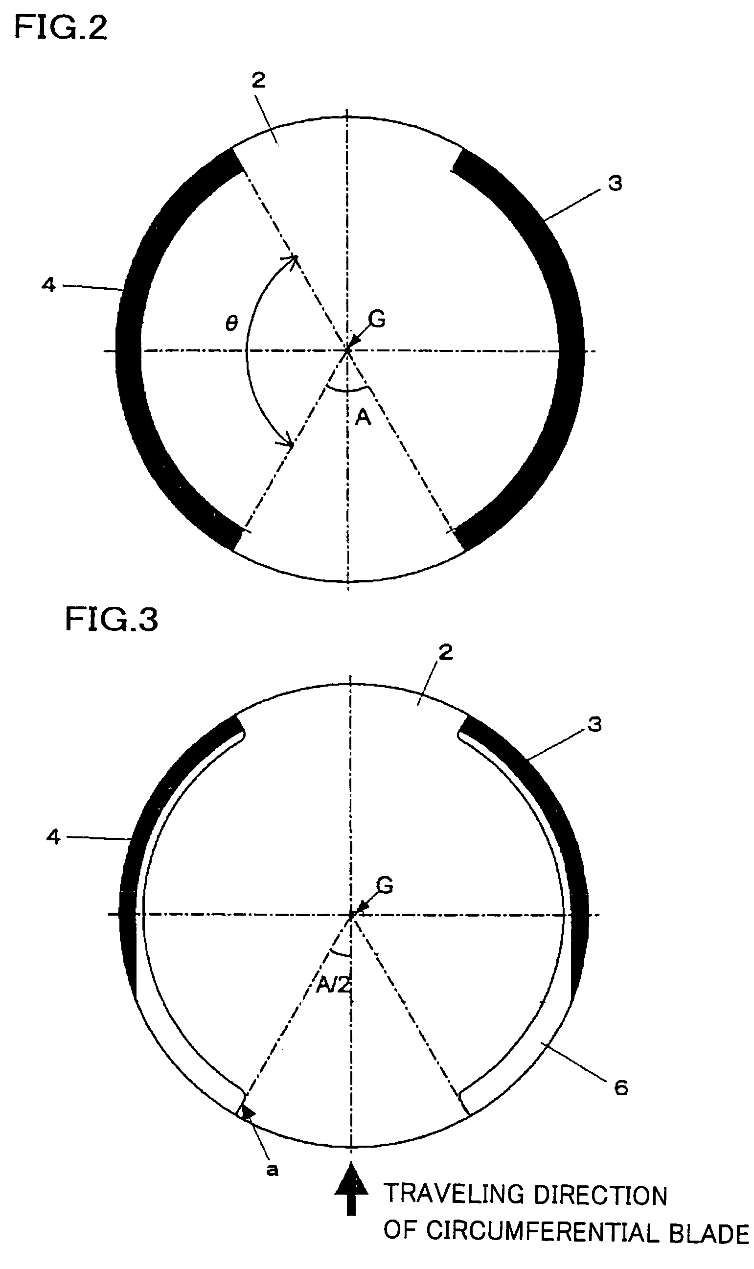
[0087]As members to be columns, there were manufactured two silicon carbide (SiC) members each of which had a cross sectional form of a circular arc with an outside radius of 165 mm, an inside radius of 147 mm, and a center angle of 120° and a length of 930 mm. And, the inside corners (corresponding to 6c in FIG. 6) of end faces in the longitudinal direction were chamfered to be R25.

[0088]As a member to be a top plate, a hollow disk with an outer diameter of 330 mm, an inner diameter of 270 mm, and a thickness of 4 mm was manufactured, and as a member to be a bottom plate, a disk with a diameter of 330 mm and a thickness of 5 mm was manufactured from SiC, respectively.

[0089]Two circular arc-shaped column members as described above were fixed between the top plate and the bottom plate by adhesion with a carbonaceous binder. At this time, the members were disposed so that an outer circumference of each of the column members accor...

example 2

[0096]Production of the Vertical Boat for Heat Treatment

[0097]As column members, there were manufactured two silicon carbide (SiC) members each of which had a cross sectional form with an outside radius of 154 mm, an inside radius of 147 mm, and a center angle of 120° and a length of 930 mm. In addition, in the outside (outer circumferential surface) of each of the members, convex parts to be beams with an outside radius of 165 mm were formed in the longitudinal direction at two places (one end and approximately middle of the circular arc) as shown in FIG. 7 (a) and the beam located on the one end of the outer circumferential surface had a center angle of 15°, and the beam near the middle thereof had a center angle of 20°, respectively.

[0098]Two column members manufactured as described above were oppositely disposed between a top plate, which was a hollow disk made of SiC with an outer diameter of 330 mm, an inner diameter of 270 mm, and a thickness of 4 mm, and a bottom plate, whic...


PUM


Abstract

A vertical boat 10 for heat treatment comprising a top plate 1, a bottom plate 2, and a column member fixed between the top plate and the bottom plate, a plurality of grooves 8 being formed in the column member, and a supporting part for horizontally supporting a wafer-like body to be treated being formed between the grooves, wherein, as the column member, two or more column members 3 and 4, each of which has a circular arc-shaped cross section and has the supporting parts in the shape of circular arc formed integrally inside by formation of the grooves, are cylindrically disposed, and the wafer-like body to be treated is inserted from the grooves of the column members and supported along a circumferential part of a lower surface thereof by the respective circular arc-shaped supporting parts. Thereby, there is provided a vertical boat for heat treatment that can effectively prevent a slip from being generated on a wafer and such during heat treatment, has low material cost, and is relatively easily produced.

Description

TECHNICAL FIELD[0001]The present invention relates to a vertical boat for heat treatment of a semiconductor wafer and such, and particularly relates to a vertical boat for heat treatment that is preferable when a silicon wafer is subjected to heat treatment and a method for producing it.BACKGROUND ART[0002]In a case that devices are produced by using a wafer cut out from a semiconductor ingot such as a silicon single crystal, there are many steps from processing of a wafer to formation of a device. There is a step of heat treatment as one of these steps. The heat treatment step is a very important process that is performed for the purpose of formation of a defect-free layer in a surface layer of a wafer, gettering, crystallization, formation of oxide film, impurity diffusion, and such.[0003]As a diffusion furnace used in such heat treatment step of a wafer such as oxidization or impurity diffusion (an apparatus for oxidization and diffusion), along with a diameter of a wafer being l...

Claims


Application Information

Patent Timeline
Patent Type & Authority Patents(United States)
IPC IPC(8): F27B5/00H01L21/683H01L21/22H01L21/31H01L21/324H01L21/673
CPCH01L21/67309H01L21/324
Inventor KOBAYASHI, TAKESHI
Owner SHIN-ETSU HANDOTAI CO LTD
Why Eureka
Try Eureka