Flush valve

a technology of flush valve and valve body, which is applied in the direction of valves, mechanical devices, engine components, etc., can solve the problems of inability to open the pilot valve, the main valve member tilting rather than the opening of the pilot valve, and the rapid movement of the actuator, so as to achieve convenient replacement, consistent and reliable flushing operation, and uniform flow rate

Active Publication Date: 2009-02-10
SLOAN VALVE COMPANY
View PDF16 Cites 21 Cited by
  • Summary
  • Abstract
  • Description
  • Claims
  • Application Information

AI Technical Summary

Benefits of technology

[0010]A primary object of the present invention is to provide an improved flush valve for supplying a measured and regulated flow of water for flushing a plumbing fixture. Other objects are to provide a flush valve having a pilot valve construction that provides a long service life and is easy to replace if worn; to provide a flush valve that achieves a consistent and reliable flushing operation when actuated at high inlet pressures that tend to clamp the pilot valve closed; to provide a flush valve with which reliable actuation is achieved if the manipulation of the actuation handle is short and rapid or tentative; to provide a flush valve in which difficulties arising from non uniform pressure caused by side water inlet are avoided; to provide a flush valve capable of maintaining a relatively uniform flow rate during the initial flush portion of a flush cycle for a siphon type toilet fixture; and to provide an improved flush valve that is relatively inexpensive, easy to manufacture and repair, and that overcomes problems experienced with known flush valves.
[0012]In brief, in accordance with another feature of the invention, there is provided a flush valve for a plumbing fixture including a housing having a longitudinal axis, an inlet, an outlet and a main valve seat between the inlet and the outlet, the main valve seat being oriented transverse to the axis. A main valve assembly includes a main valve member movable in the axial direction relative to the main valve seat. The main valve assembly includes a pilot valve seat. A pilot valve member moves relative to the pilot valve seat. A control chamber is located at a first side of the main valve member. A restricted passage between the inlet and the control chamber normally pressurizes the control chamber and holds the main valve member against the main valve seat and the pilot valve member against the pilot valve seat. A stem extends axially from the pilot valve member in a first axial direction away from the control chamber. The stem has an end portion and an intermediate portion between the end portion and the pilot valve. An actuator is engageable with the intermediate portion of the stem for tilting the pilot valve by laterally moving the stem in order to exhaust the control chamber and permit axial movement of the main valve assembly in an opposed second axial direction. An enlargement at the end portion of the stem is engageable with the actuator during the axial movement in the second direction for further lateral movement of the stem and further tilting of the pilot valve.
[0014]In brief, in accordance with another feature of the invention, there is provided a flush valve for providing a metered flushing water flow to a plumbing fixture. The flush valve includes a housing having an inlet, an outlet and a main valve seat, and a tubular wall defining an outlet passage extending from a first side of the main valve seat toward the outlet. An annular inlet chamber surrounds the tubular wall and communicates with the inlet and with the main valve seat. A main valve assembly includes a main valve member movably toward the main valve seat to a closed position and away from the main valve seat to a full open position. A normally pressurized control chamber is in the housing at a second side of the main valve seat. The main valve assembly includes a sealing member between the main valve member and the housing for isolating the control chamber from the inlet chamber. A pilot valve assembly is operable from a blocked position to a vent position for venting the control chamber to the outlet and moving the main valve member in the control chamber from the closed position to the full open position. A stop in the control chamber is engageable with the pilot valve assembly in the full open position of the main valve member for holding the pilot valve assembly in its blocked position. A restricted passage extendes between the inlet chamber and the control chamber for repressurizing the control chamber and returning the main valve member from the full open position to the closed position. First and second flow throttling assemblies are formed on the housing and on the main valve assembly. The first flow throttling assembly has a minimum throttling effect in the full open position of the main valve and provides increasing flow throttling as the main valve member moves toward the closed position. The second flow throttling assembly has a maximum throttling effect in the full open position of the main valve and provides decreasing flow throttling as the main valve member moves toward the closed position.

Problems solved by technology

One problem with known flush valves is unreliable and inconsistent initiation of a flush cycle under high inlet pressure conditions.
Inlet pressure can clamp the pilot valve closed tightly, and tilting of the pilot valve and stem can result in tilting of the main valve member rather than opening of the pilot valve.
Another problem encountered with known flush valves occurs when the actuator tilts the pilot valve stem only slightly.
A short, rapid movement of the actuator may fail to open the pilot valve and vent the control chamber due to factors such as inertia of the pilot valve.
Water flowing through the valve enters from the side and then flows up and over the main valve seat with a non uniform pressure and flow pattern resulting from the effect of side entry velocity.
Side loading can cause friction, reducing valve life, as well as inconsistent flush volume.
In addition, the nonuniform water pressure field in the control chamber results in flush valve operation being sensitive to location of elements such as the restricted orifice.
Another problem with known flush valves is pilot valve wear.
Wear results from repeated valve operation, and replacement and repair is difficult.
However, known flow throttling arrangements do not overcome the problem of continuously decreasing flow as the valve closes.

Method used


Image

  • Flush valve
  • Flush valve
  • Flush valve

Examples


Embodiment Construction

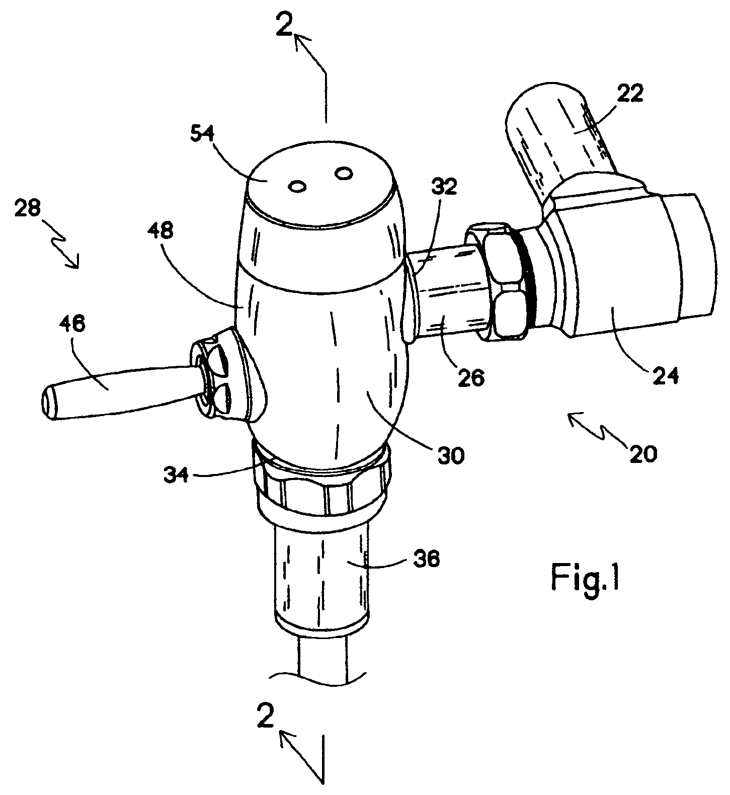
[0029]Having reference now to the drawing, and initially to FIG. 1, there is illustrated a plumbing installation generally designated as 20 for flushing a toilet fixture (not shown). The plumbing installation 20 has a water supply conduit 22 through which water is supplied from a pressurized source such as a municipal or local water supply system. Conduit 22 supplies water to a throttling control stop 24, and water from the control stop 24 is supplied through a transfer conduit 26 to a flush valve generally designated as 28 and constructed in accordance with the principles of the present invention.

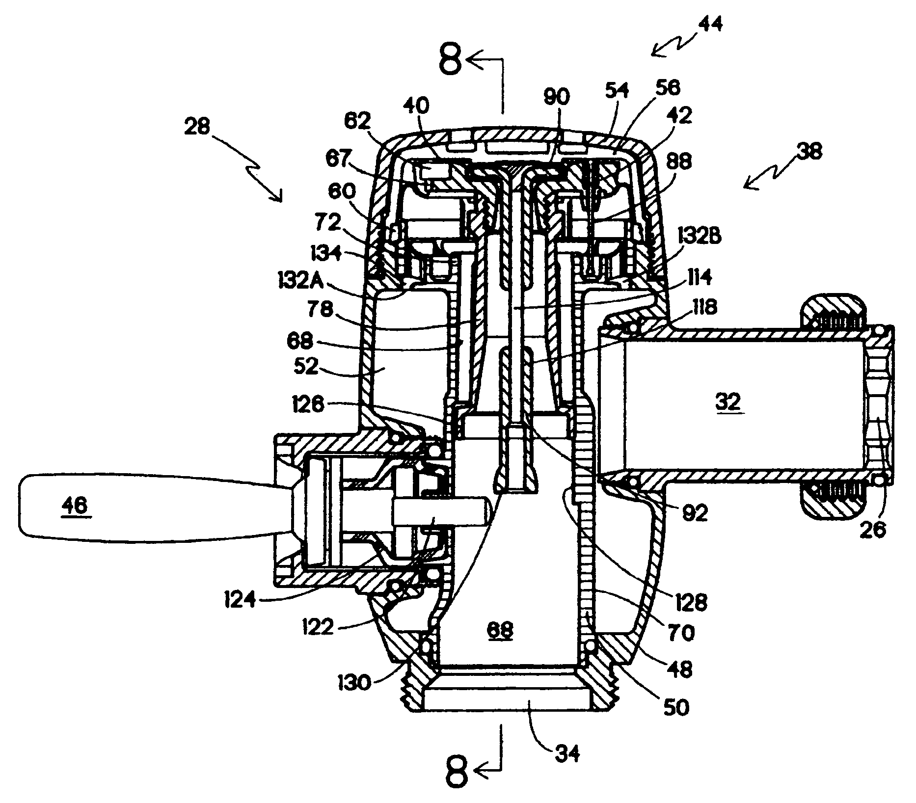
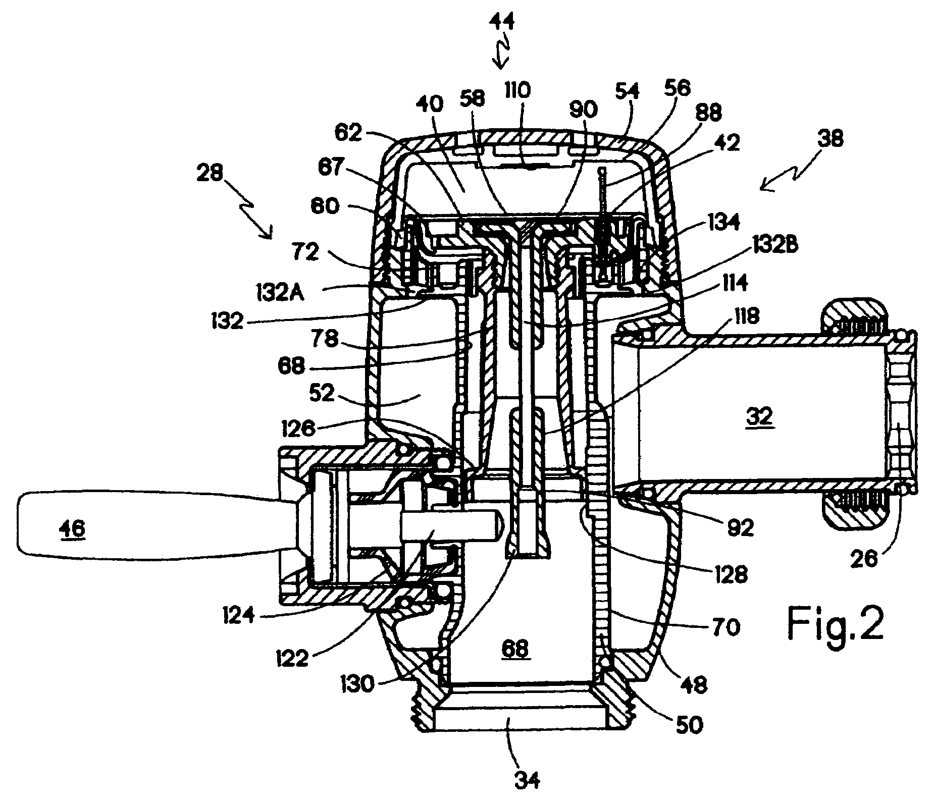
[0030]The flush valve 28 of the present invention is illustrated in detail in FIGS. 2-12. In general the flush valve 28 includes a housing assembly 30 with an inlet 32 connected to the conduit 26 and an outlet 34 adapted to be connected to an outlet conduit 36 (FIG. 1). A main valve assembly 38 is movable between a closed position (FIG. 2) and a full open position (FIG. 5) to control flow ...


PUM


Abstract

Tilting of a main valve assembly in unison with the head portion of a pilot valve under high inlet pressure conditions is prevented by supporting the main valve assembly with housing rib engaging a skirt on the main valve guide tube opposed to the handle actuated push rod. A positive, toggle like pilot valve opening results from contact of an enlargement on the pilot valve stem with the push rod as the pilot valve begins its upward movement. An off center baffle in the inlet passage compensates for the non uniform pressure pattern resulting from the side entry inlet. The pilot valve head includes an easily replaceable cup shaped seal having a reentrant rim engaging the pilot valve surface in the main valve member and having an upper central portion engaging an abutment with a valve rotator configuration is the full open position. A secondary throttling structure provided by a skirt on the guide tube cooperating with a shoulder in the outlet passage provides a desirable large flush flow for siphon fixtures.

Description

FIELD OF THE INVENTION[0001]The present invention relates to an improved flush valve for plumbing fixtures.DESCRIPTION OF THE PRIOR ART[0002]Flushing systems for toilet fixtures in applications such as commercial structures normally include a flush valve supplying water to flush each fixture. The flush valve is conventionally a flushometer type, operating to supply a measured or metered volume of water for the flushing operation. Examples of conventional flush valves are disclosed in U.S. Pat. No. 4,327,891 and U.S. Pat. No. 5,295,655. Another flush valve is disclosed in U.S. Pat. No. 4,662,602.[0003]A typical flush valve includes a main valve to control flow through the flush valve from an inlet to an outlet. Inlet pressure in a control chamber normally holds the main valve member closed against the main valve seat. A seal, typically a diaphragm with a portion of the diaphragm, or an element supported by the diaphragm, serving as a main valve member, isolates the control chamber fr...

Claims


Application Information

Patent Timeline
Patent Type & Authority Patents(United States)
IPC IPC(8): F16K31/12
CPCE03D3/06F16K31/145F16K31/3855
Inventor JOHNSON, DWIGHT N.
Owner SLOAN VALVE COMPANY
Why Eureka
Try Eureka