Electronic ballast having adaptive frequency shifting

a technology of electronic ballast and frequency shifting, which is applied in the field of electronic ballasts, can solve the problems of increasing the cost of microprocessors, affecting the operation of the system, so as to achieve the effect of minimizing the target duty cycle and operating the duty cycl

Inactive Publication Date: 2009-02-10
LUTRON TECH CO LLC
View PDF8 Cites 38 Cited by
  • Summary
  • Abstract
  • Description
  • Claims
  • Application Information

AI Technical Summary

Benefits of technology

[0022]According to the present invention, an electronic ballast for driving a gas discharge lamp includes an inverter, a resonant tank, a control circuit, and a current sense circuit. The inverter converts a substantially DC bus voltage to a high-frequency AC voltage having an operating frequency and an operating duty cycle. The resonant tank couples the high-frequency AC voltage to the lamp to generate a present lamp current through the lamp. The control circuit is operable to control the operating frequency and the operating duty cycle of the high-frequency AC voltage of the inverter. The current sense circuit provides to the control circuit a present lamp current signal representative of the present lamp current. The control circuit is operable to control the operating duty cycle of the high-frequency AC voltage of the inverter in response to a target lamp current signal and the present lamp current signal. Further, the control circuit is operable to control the operating frequency of the high-frequency AC voltage of the inverter in response to the operating duty cycle and a target duty cycle, such that the control circuit is operable to minimize the difference between the operating duty cycle and the target duty cycle. Preferably, the control circuit is further operable to control the operating frequency to a base operating frequency in dependence on the target lamp current signal, when the target lamp current changes in value.
[0023]The present invention further provides a method for controlling an electronic ballast for driving a gas discharge lamp. The ballast comprises an inverter characterized by an operating frequency and an operating duty cycle. The method comprises the steps of generating a present lamp current through the gas discharge lamp in response to the operating frequency and the operating duty cycle of the inverter; generating a present lamp current signal representative of the present lamp current; receiving a target lamp current signal representative of a target lamp current; controlling the duty cycle of the inverter in response to the target lamp current signal and the present lamp current signal; and controlling the operating frequency of the inverter in response to the target lamp current signal, the operating duty cycle of the inverter, and a target duty cycle, such that the difference between the operating duty cycle and the target duty cycle is minimized.
[0024]In addition, the present invention provides a control circuit for an electronic ballast having an inverter for driving a gas discharge lamp. The control circuit is operable to control an operating frequency and an operating duty cycle of the inverter of the ballast. The control circuit comprises a duty cycle control portion for controlling the operating duty cycle of the inverter in response to a target lamp current signal and a present lamp current signal, and a frequency control portion for controlling the operating frequency of the inverter in response to the target lamp current signal, the operating duty cycle, and a target duty cycle. The difference between the operating duty cycle and the target duty cycle is minimized.

Problems solved by technology

An alternative would be to provide additional circuitry to clamp the output of the compensator circuit 216 at a given level during preheat, but this would add additional cost and complexity.
The high current, along with the time required for the loop to come out of saturation, can result in a noticeable flash when the lamps strike.
This can be improved with a higher resolution ADC or a higher sampling rate, but as mentioned earlier, higher capability results in higher cost for the microprocessor 350.
One complication that results from operating the inverter 104 at a frequency that is away from the resonant frequency when utilizing the d(1−d) switching scheme (i.e., at high-end) is the possibility of “mercury pumping”.
As a result, the lamp current is not symmetric.
The constraints of being able to reach high-end in the worst case while having the highest duty cycle possible result in the need for tight tolerances on components and the need to tailor tank component values to a narrow load range.

Method used


Image

  • Electronic ballast having adaptive frequency shifting
  • Electronic ballast having adaptive frequency shifting
  • Electronic ballast having adaptive frequency shifting

Examples


second embodiment

[0060]FIG. 9 is a control system diagram illustrating the control loops of a ballast 900 according to the present invention. The ballast 900 is operable to control the operating frequency of the ballast in response to only the operating duty cycle and the target duty cycle. In this embodiment, the ballast 900 is not operable to control the operating frequency in dependence upon the target lamp current. The ballast 900 is operable to drive the lamp 108 such that mercury pumping is avoided. However, when the target lamp current changes, the actual lamp current, and thus the lamp intensity, changes at a slower rate than in the previous embodiment, since the operating frequency control loop, i.e., the duty cycle error value ed, is solely in control of the operating frequency.

[0061]FIG. 10 is a flowchart of the software executed by the microprocessor of the ballast 900 to adaptively change the operating frequency fOP according to the second embodiment of the present invention. Steps 1002...

third embodiment

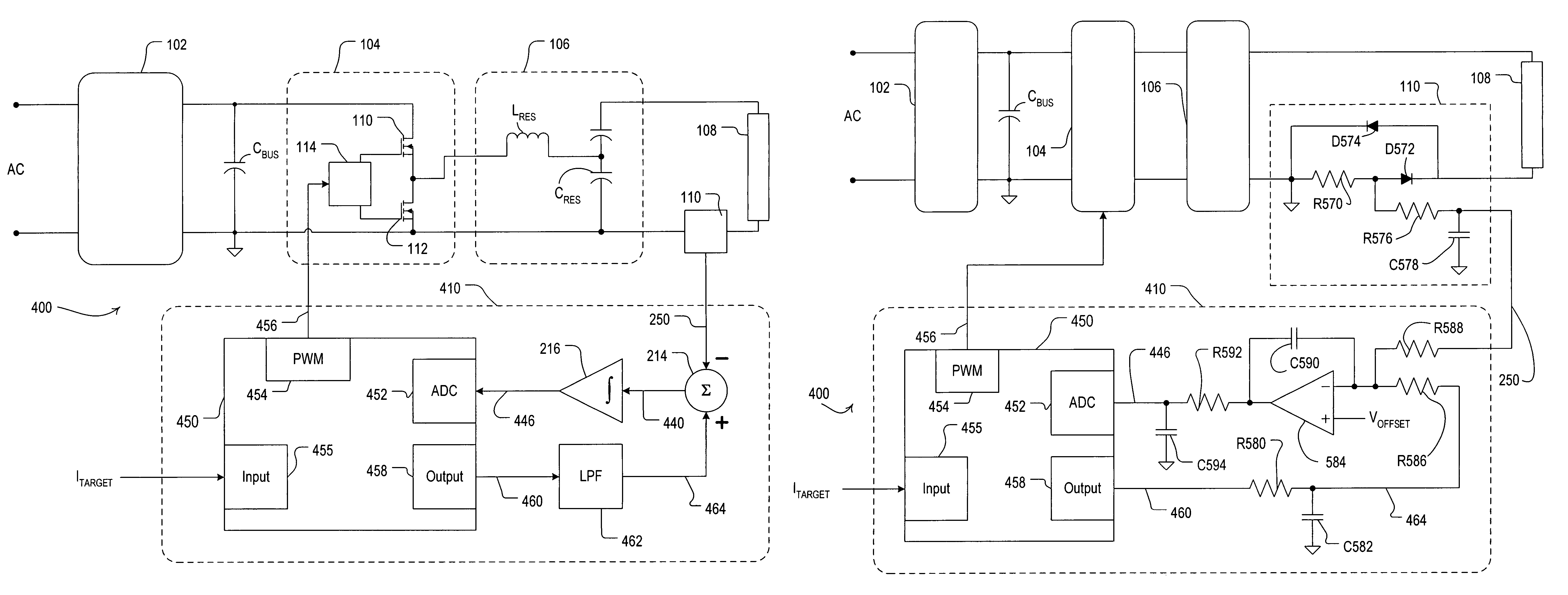
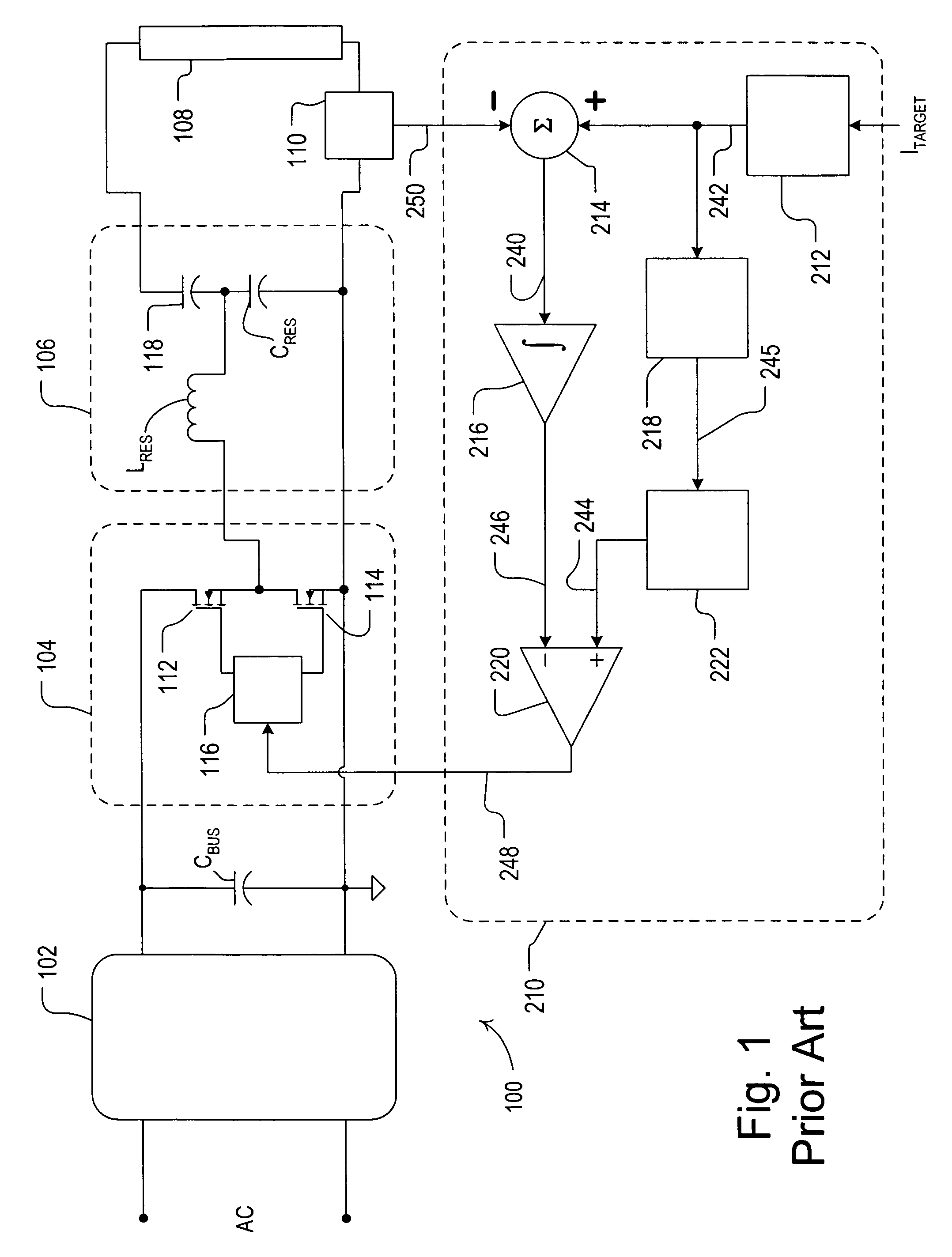
[0063]FIG. 11 is a simplified schematic diagram of a ballast 1100 according to the present invention. The ballast 1100 has an entirely analog control circuit 1110, with a control loop for control of the operating duty cycle dOP and another control loop for control of the operating frequency fOP. The components of the duty cycle control loop, i.e., the reference circuit 212, the summing circuit 214, and the compensator circuit 216, operate the same way as those components of the analog control circuit 210 of the prior art ballast 100 to produce a PWM signal 1170 characterized by the operating duty cycle dOP and the operating frequency fOP at the output of the comparator 220.

[0064]However, the analog control circuit 1110 uses the operating duty cycle dOP as feedback to determine the operating frequency fOP. The PWM signal 1170 is provided to a low pass filter (LPF) 1172 to produce a first DC reference signal 1174 representative of the duty cycle of the PWM signal 1170. A reference cir...


PUM


Abstract

An electronic ballast for driving a gas discharge lamp avoids mercury pumping in the lamp by adaptively changing an operating frequency of an inverter of the ballast when operating near high-end. The inverter of the ballast generates a high-frequency AC voltage, which is characterized by the operating frequency and an operating duty cycle. The ballast also comprises a resonant tank for coupling the high-frequency AC voltage to the lamp to generate a present lamp current through the lamp, and a current sense circuit for determining the magnitude of the present lamp current. A hybrid analog / digital control circuit controls both the operating frequency and the operating duty cycle of the inverter with closed-loop techniques. The control circuit adjusts the duty cycle of the inverter in response to a target lamp current and the present lamp current. To avoid mercury pumping, the control circuit attempts to maximize the duty cycle of the inverter when operating at high-end. Specifically, the control circuit adjusts the operating frequency of the inverter in response to the target lamp current signal, the duty cycle of the inverter, and a target duty cycle in order to drive the operating duty cycle toward the target duty cycle.

Description

FIELD OF THE INVENTION[0001]The present invention relates to electronic ballasts and, more particularly, to electronic dimming ballasts for gas discharge lamps, such as fluorescent lamps.BACKGROUND OF THE INVENTION[0002]Electronic ballasts for fluorescent lamps typically can be analyzed as comprising a “front-end” and a “back-end”. The front-end typically includes a rectifier for changing alternating-current (AC) mains line voltage to a direct-current (DC) bus voltage, and a filter circuit, e.g., a capacitor, for filtering the DC bus voltage. The front-end of electronic ballasts also often includes a boost converter, which is an active circuit for boosting the magnitude of the DC bus voltage above the peak of the line voltage and for improving the total harmonic distortion (THD) and the power factor of the input current to the ballast. The ballast back-end typically includes a switching inverter for converting the DC bus voltage to a high-frequency AC voltage, and a resonant tank ci...

Claims


Application Information

Patent Timeline
Patent Type & Authority Patents(United States)
IPC IPC(8): G05F1/00
CPCH05B41/2828H05B41/3925
Inventor TAIPALE, MARK S.
Owner LUTRON TECH CO LLC
Why Eureka
Try Eureka