System for designing, previewing, and cutting natural stone veneer to deliver ready for installation

a natural stone veneer and installation system technology, applied in the direction of instruments, manufacturing tools, and investigating machinability, can solve the problems of not having the chance to preview the overall pattern, manual, multi-step, labor-intensive methods, etc., and achieve the effect of facilitating installation and greater design potential

Inactive Publication Date: 2009-02-10
NEW WORLD STONEWORKS
View PDF16 Cites 12 Cited by
  • Summary
  • Abstract
  • Description
  • Claims
  • Application Information

AI Technical Summary

Benefits of technology

[0036]The present invention has many advantages. The methods according to various embodiments of the invention provide a process for cutting natural stone according to a predetermined veneer design and finishing the edge of the resulting stone veneer components. A significant amount of effort and time is saved in bringing the stone from raw material to a condition wherein it is ready for installation, fit with other natural veneer stones prepared in this process.
[0052]Delivery of precut veneer stones of predetermined perimeter contours facilitates installation to the extent that a relatively un-skilled homeowner could install the stones by using a kit according to an embodiment of the invention, without help from a mason or construction worker. Accordingly, a skilled mason could install the disclosed stone veneer components more precisely, more quickly, and with greater design potential than by using existing methods for installing natural stone in a veneer application.

Problems solved by technology

There is currently no easy-to-use technique available for designing, cutting and installing uniformly-fitting natural stone veneer components.
Only manual, multi-step, labor-intensive methods are available for cutting and finishing the edges on natural stone veneer components.
None of the current techniques offer the chance to preview the overall patterns of natural stone veneer components in advance of installation or amend a design before it is installed.
Starting with pallets of raw stone and cutting individual stones on a jobsite is an extremely time consuming undertaking that can prove challenging when managing a large project with tight deadlines.
Further, typical techniques for dry-cutting natural stone at a jobsite generate potential health hazards from airborne stone dust, produce a messy work environment and cause damage to surrounding landscaping due to extended worker activity in the area.
These environmental problems are of great concern particularly when the work is being done at an occupied residence or commercial location.
Use of artificial stone veneer generally does not provide a means to preview the exact layout pattern of individual pieces prior to installation.
Further, cutting artificial stones to fit around openings such as doors or windows, exposes unattractive cement aggregates.
However, prior to our discovery, there has been no method for practical or reliable use of a water jet for cutting the rough, irregular surface common to veneer stone.
Prior to the disclosed methods, no one has drawn complete design plans for the actual cutting patterns of interconnecting veneer stone components for a project.
The instructions of the manufacturer generally warn that if the waterjet is not kept close to the surface of the material, the pressure of the waterjet and the concentration of abrasive may be diminished such that the cut will not be clean or precise.
None of these systems are able to reliably navigate the extremely rough and irregular surfaces characteristic of the type of veneer stone described herein.

Method used


Image

  • System for designing, previewing, and cutting natural stone veneer to deliver ready for installation
  • System for designing, previewing, and cutting natural stone veneer to deliver ready for installation
  • System for designing, previewing, and cutting natural stone veneer to deliver ready for installation

Examples


example

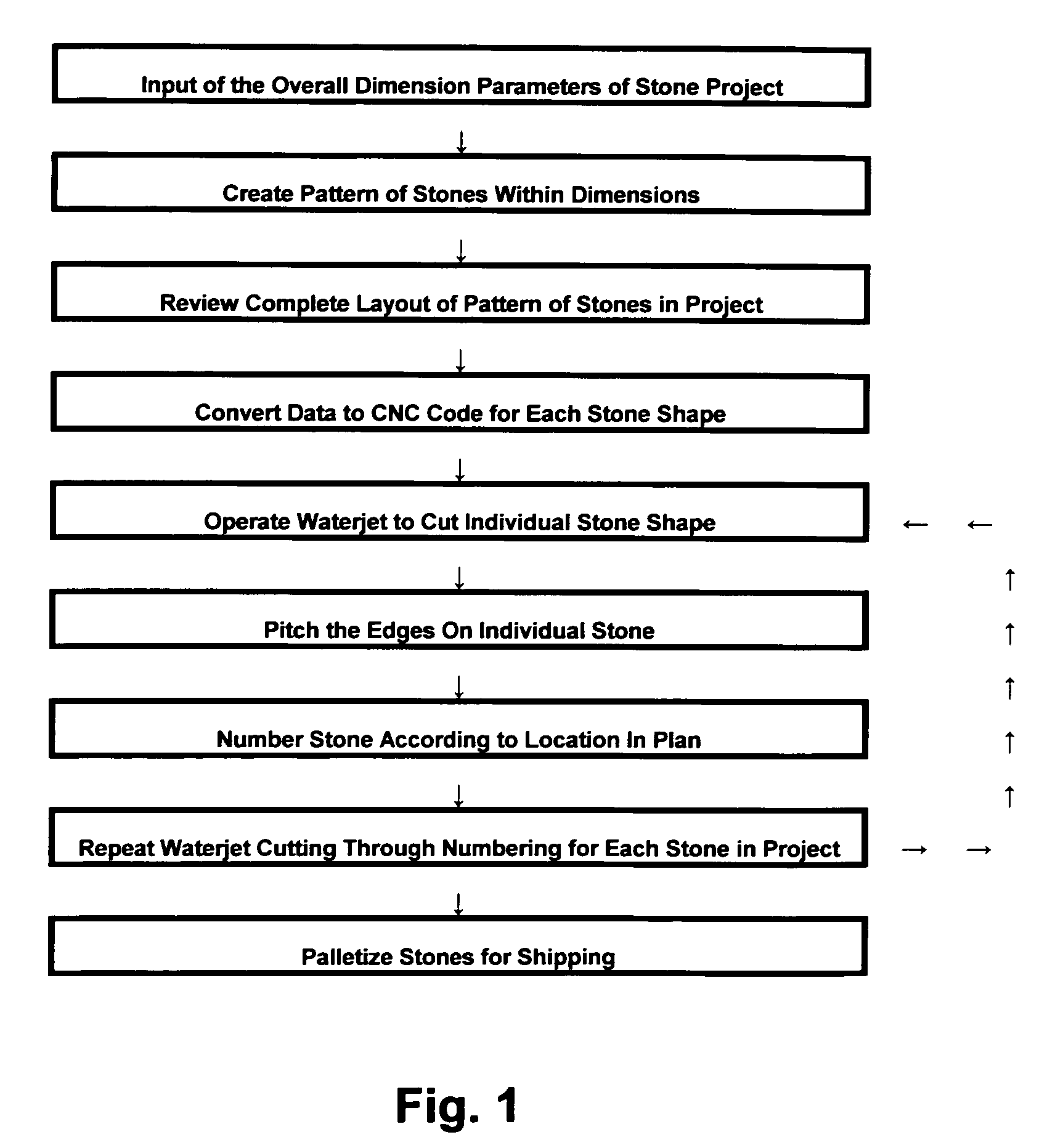
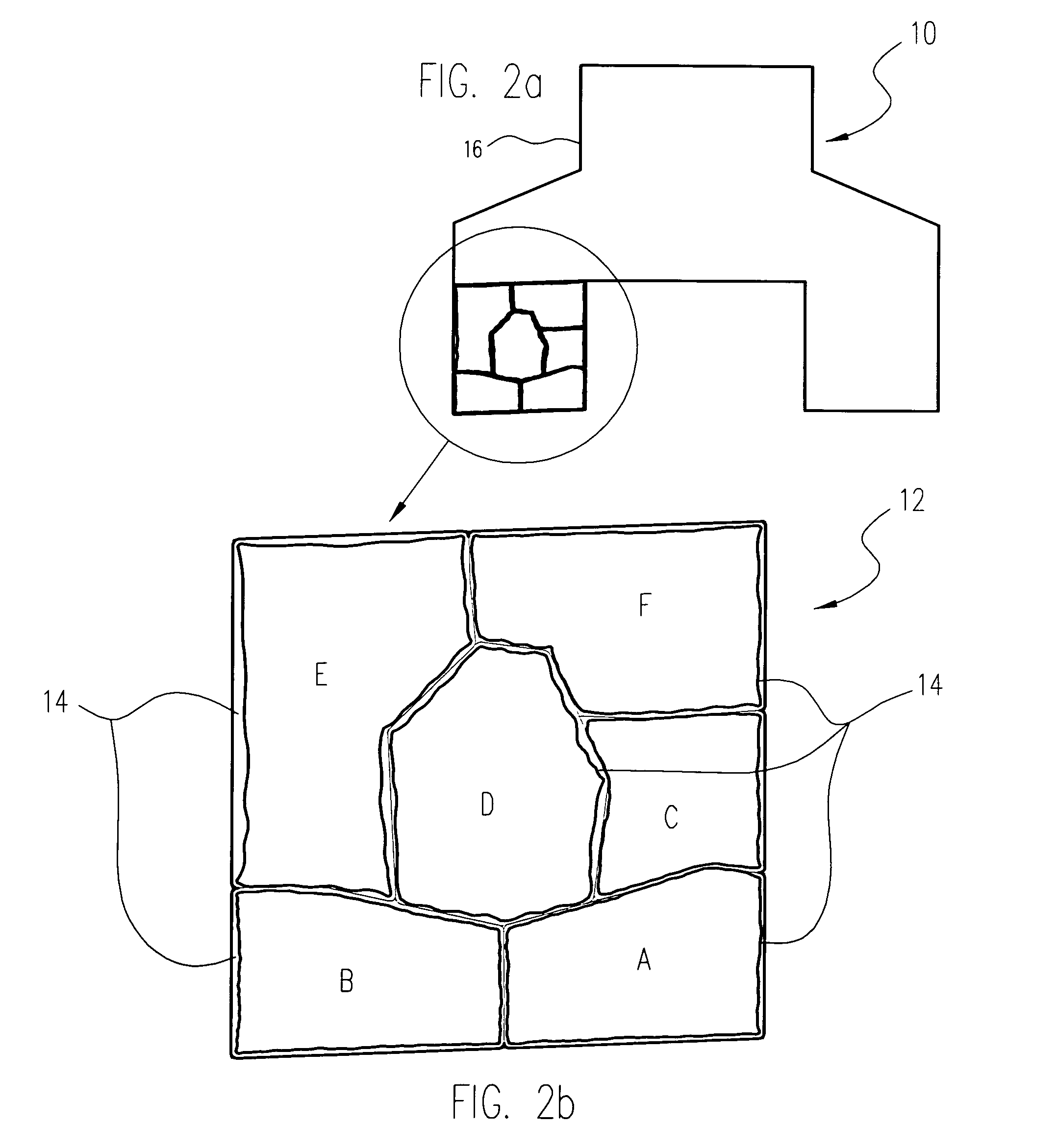
[0095]1) We set up the Computer Aided Design (CAD) file of the complete project and how it will look when fully installed. We started with the overall dimensions and profile of the installation and then filled in the middle area with the intersecting pieces to create the design pattern. This enabled us to print out a design proof for the customer and make any changes necessary to receive approval from the customer on the design. In this way, the customer can view a digital representation of how the natural stone veneer components will look when cut and installed in the finished project.

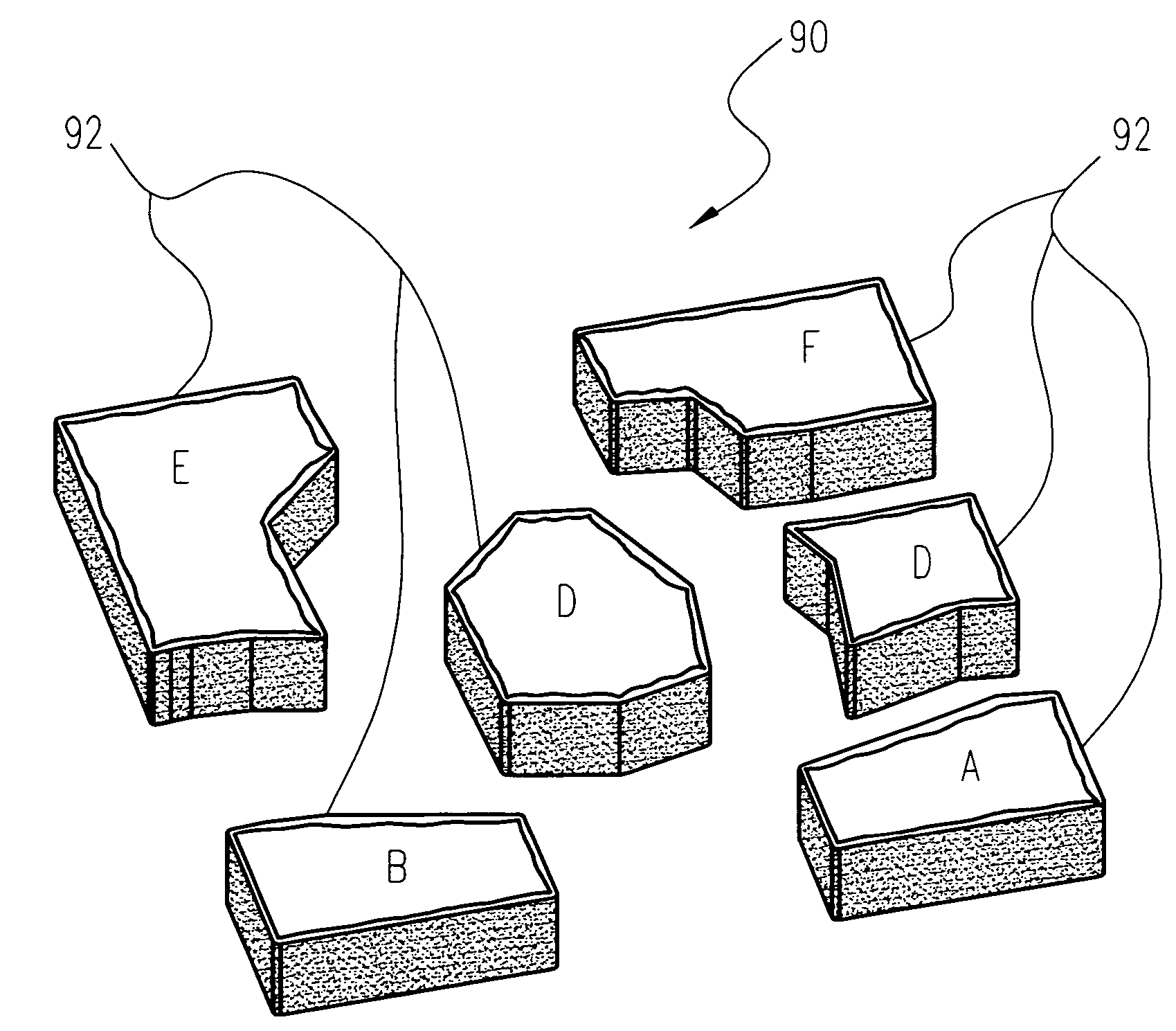
[0096]2) We then broke apart the design into individual components that were to be cut. For the design plan for the project, each component was of unique shape. Optionally, there can be certain components that repeat throughout the pattern, and for such shapes, we cut the appropriate numbers of that same shape.

[0097]3) We converted the CAD design for each unique component to a machine readable format ...


PUM

PropertyMeasurementUnit
thicknessaaaaaaaaaa
distanceaaaaaaaaaa
pressureaaaaaaaaaa

Abstract

The present invention relates to a method of designing, previewing a stone veneer project in its entirety before a single stone is cut; cutting and finishing the edges of a stone to form interconnecting natural stone veneer components, each having a perimeter of a pre-determined contour and a finished edge, the method comprising: drawing or otherwise importing a design plan comprising overall dimensions and shape of a finished stone veneer project; drawing or otherwise importing a pattern of shape and placement of the stone veneer components within the design plan; programming, scanning or otherwise inputting a plurality of cutting patterns, wherein the cutting patterns are the same or different, each cutting pattern designed to form the stone veneer component having a perimeter of a pre-determined contour; converting the pattern into a machine-readable program to produce a cutting path on an abrasive waterjet machine; loading a cutting path file for the stone veneer component into the abrasive water jet machine; positioning a cutting head of the waterjet machine over the natural stone at a distance of from about 0.3 inch to about 4 inches from a contact surface of the stone; running the cutting path program and cutting through the stone by contacting the contact surface of the stone with a waterjet from the waterjet machine.

Description

BACKGROUND OF THE INVENTION[0001]There is currently no easy-to-use technique available for designing, cutting and installing uniformly-fitting natural stone veneer components. Stone used for veneer is generally less than 2 inches in thickness. Only manual, multi-step, labor-intensive methods are available for cutting and finishing the edges on natural stone veneer components. None of the current techniques offer the chance to preview the overall patterns of natural stone veneer components in advance of installation or amend a design before it is installed.[0002]Starting with pallets of raw stone and cutting individual stones on a jobsite is an extremely time consuming undertaking that can prove challenging when managing a large project with tight deadlines. Further, typical techniques for dry-cutting natural stone at a jobsite generate potential health hazards from airborne stone dust, produce a messy work environment and cause damage to surrounding landscaping due to extended worke...

Claims


Application Information

Patent Timeline
Patent Type & Authority Patents(United States)
IPC IPC(8): G01N3/58B24C1/00B24C1/04B24C3/32
CPCB24C1/045B24C3/04B24C7/0007B28D1/00B28D1/006B28D1/30
Inventor JACKMAN, KENNETHBACA, III, JOSEPH E.
Owner NEW WORLD STONEWORKS
Why Eureka
Try Eureka