Vaporizer that vaporizes a liquid to generate vapor

a technology of vaporizer and liquid fuel, which is applied in the field of vaporizer, can solve the problems of difficult to obtain satisfactory response, ineffective utilization of fuel vapor energy, and inability to effectively utilize energy possessed by fuel vapor, etc., and achieve excellent response, effective utilization of energy, and extremely efficient vaporization of liquid fuel

Inactive Publication Date: 2009-02-17
HONDA MOTOR CO LTD
View PDF27 Cites 21 Cited by
  • Summary
  • Abstract
  • Description
  • Claims
  • Application Information

AI Technical Summary

Benefits of technology

[0013]Therefore, the present invention provides a vaporizer that is able to vaporize liquid fuel extremely efficiently by effectively utilizing energy, and has excellent response.
[0014]In addition, the present invention provides a vaporizer that reduces any loss of pressure on the gas flow path while enabling the size of the apparatus to be reduced.

Problems solved by technology

However, in this conventional vaporizer, in some cases a portion of the liquid fuel that is supplied to the vaporization chamber from the fuel supply apparatus is unable to be vaporized as it passes through the group of tubes, and is left on the bottom of the vaporization chamber in a liquid state.
If liquid fuel is left in a liquid state on the bottom of the vaporization chamber in this manner, then it is not possible for the quantity of generated vapor (i.e., the quantity of generated raw fuel gas) during a transition to match the output from the fuel cell, so that the problem arises that the response is deteriorated.
Moreover, even if a heating source such as a catalytic combustor is placed on the bottom of the vaporization chamber so as to reduce the quantity of liquid left behind, it is still difficult to obtain a satisfactory response.
However, in this vaporizer, because the fuel vapor flows downwards in the gravitational direction inside the vaporization flow path so as to be in a parallel flow relationship with the liquid fuel, it is not possible to effectively utilize the energy possessed by the fuel vapor.
Furthermore, in a conventional vaporizer, because combustion gas is introduced into a large number of tubes that have been bent substantially in a U-shape and is circulated through these tubes, there is a considerable pressure loss in the fuel gas.
Accordingly, in order to increase the fuel gas flow rate so as to increase the heat quantity, it has been necessary to increase the number of tubes, thereby creating the problem that the size of the evaporator has increased.
In other words, the size of the pressure loss on the fuel gas flow path is an obstacle to reducing the size of the vaporizer.
Moreover, when a combustion catalyst is supported inside the tubes, it is not possible to secure a sufficient catalytic layer volume.
Note that, in the above description, the term “response” is a characteristic that expresses a temporal delay when vapor is generated and supplied to match the required quantity that is determined based on a varying output from a fuel cell, and a “poor response” refers to the fact that this delay is sizeable.

Method used


Image

  • Vaporizer that vaporizes a liquid to generate vapor
  • Vaporizer that vaporizes a liquid to generate vapor
  • Vaporizer that vaporizes a liquid to generate vapor

Examples


first embodiment

[0062]Firstly, the first embodiment of the present invention will be described with reference made to FIG. 1 through FIG. 5.

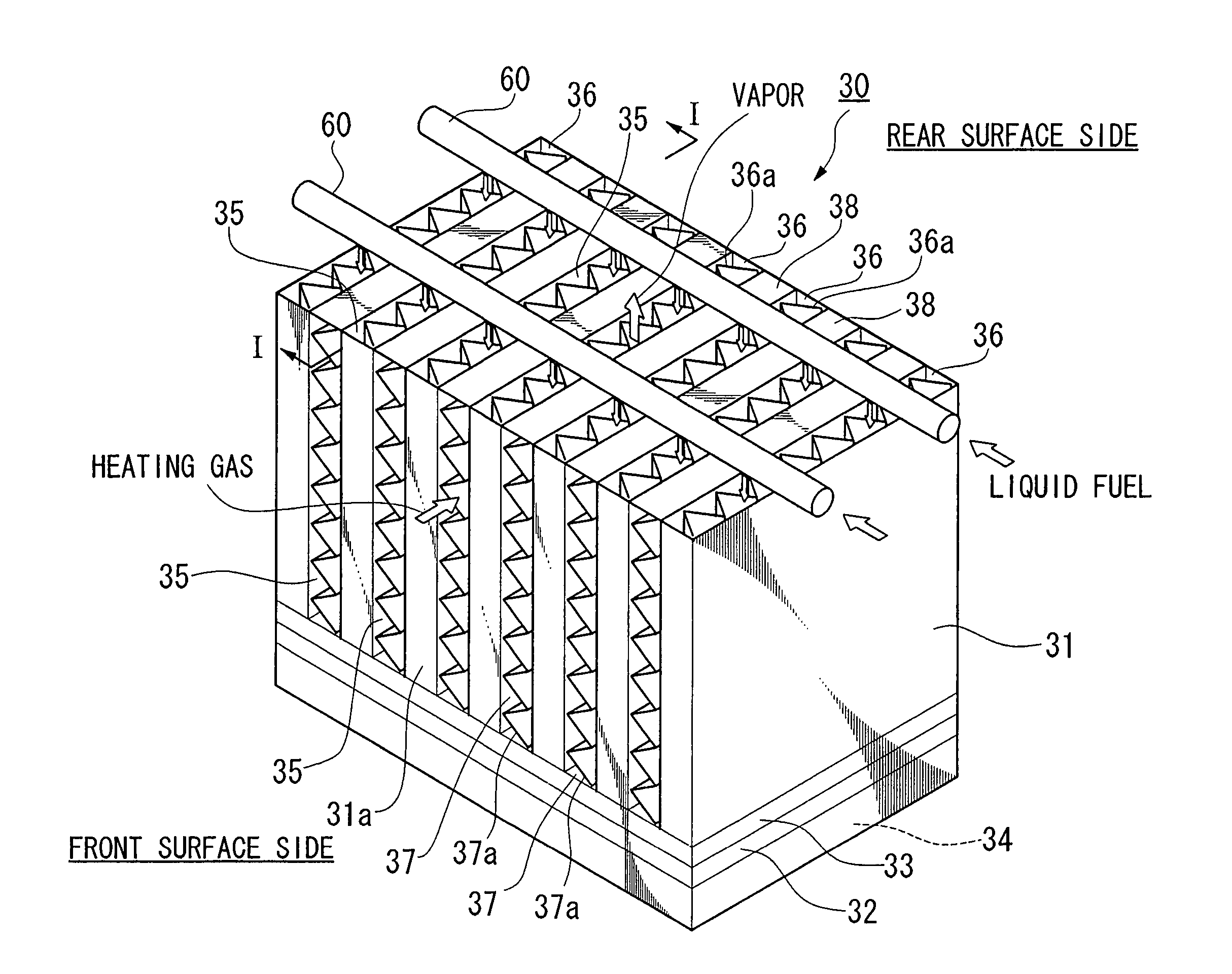
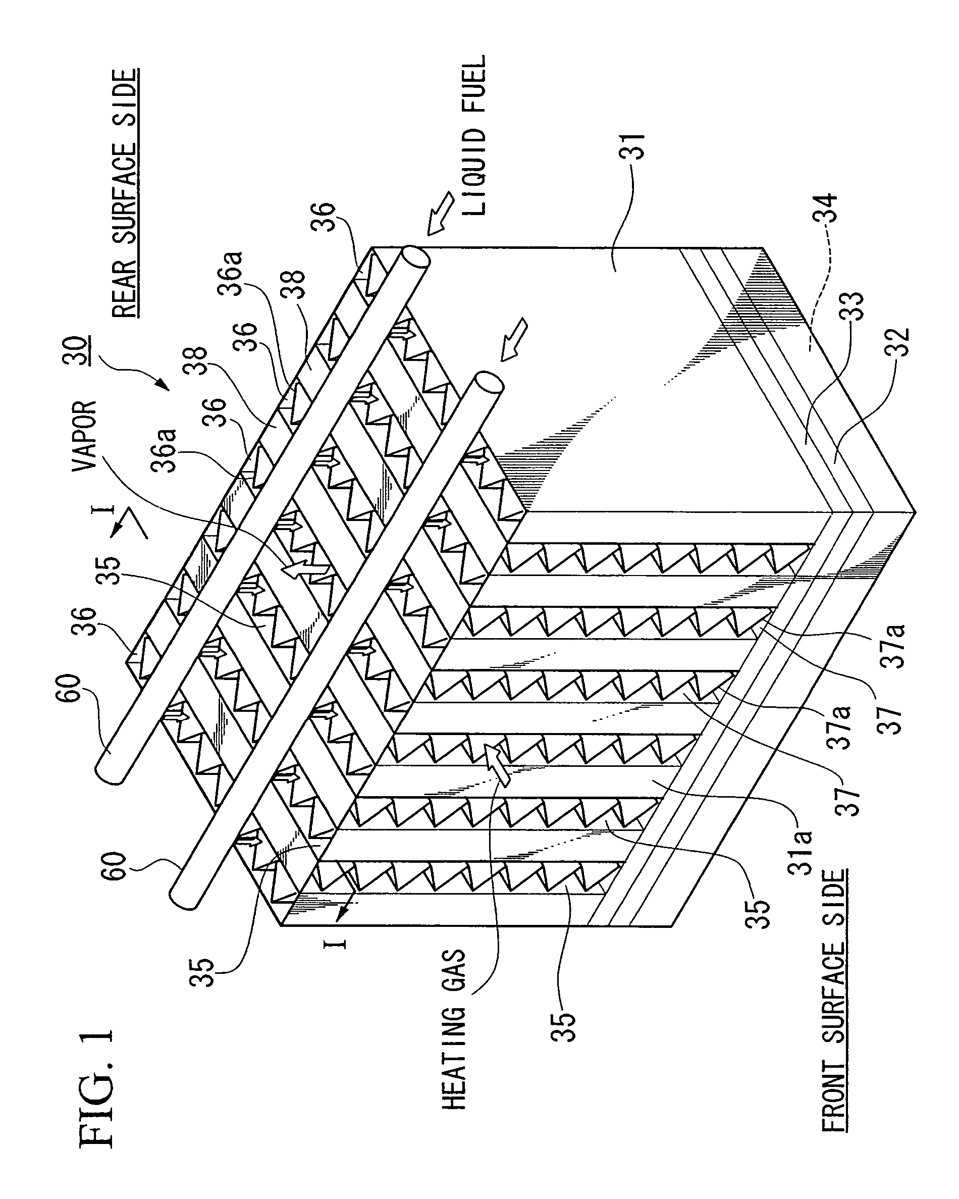
[0063]FIG. 1 is a schematic structural view of a vaporizer 30. The vaporizer 30 is provided with a case 31 having the shape of a rectangular parallelepiped. A porous material 33 is mounted on the top side of a bottom plate (i.e., a bottom portion) 32 of the case 31, and a heating chamber (i.e., the heating apparatus) 34 is provided on the bottom side of the bottom plate 32.

[0064]The interior of the case 31 above the porous material 33 is divided into a large number of narrow width chambers that are formed in parallel with each other by partitioning walls 35, and these chambers are formed alternatingly as vaporization flow paths 36 and heating gas flow paths 37, with the outermost chamber in all cases being a vaporization flow path.

[0065]Each of the vaporization flow paths 36 is open only at the top, and bottom portions thereof are blocked by the bottom plate 32...

second embodiment

[0088]The second embodiment of the vaporizer 30 of the present invention will now be described with reference made to FIGS. 6 through 8. The vaporizer 30 of the second embodiment differs from that of the first embodiment in the following points.

[0089]In the vaporizer 30 of the first embodiment, the respective heating gas flow paths 37 are completely open on the front surface side and the rear surface side of the case 31, however, in the vaporizer 30 of the second embodiment, on the front surface side of the case 31, only the top portion and bottom portion of the respective heating gas flow paths are open, and on the rear surface side of the case 31, the entire surface of the respective heating gas flow paths 37 are blocked. Moreover, an aperture 37c that is provided on the bottom side of the front surface side of the case 31 forms a heating gas intake aperture, while an aperture 37d that is provided on the top side thereof forms a heating gas discharge aperture. Between the aperture...

third embodiment

[0094]Note that the present invention is not limited to the above described embodiments.

[0095]For example, the shape of the fins 36a provided inside the vaporization flow paths 36 is not limited to a substantially triangular waveform shape, and a variety of shapes, such as those shown in FIGS. 9A to 9E, can be employed. FIG. 9A is a fin having a rectangular waveform-shaped cross-section, FIG. 9B is what is known as a heliborne fin, FIG. 9C is a multi-hole plate fin, FIG. 9D is what is known as a cellate fin, and FIG. 9E is what is known as a louver fin.

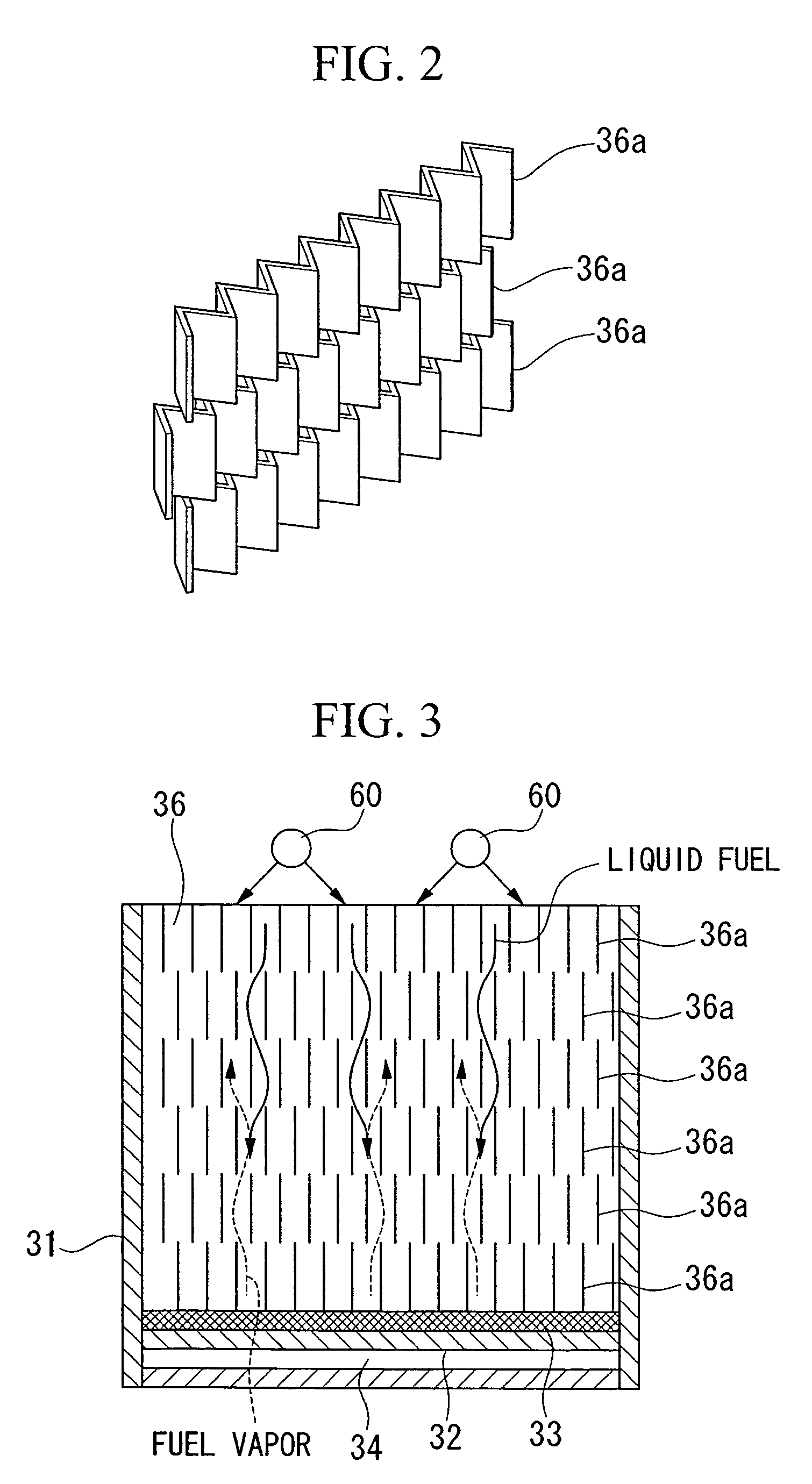
[0096]In addition, in the above described embodiments, the fins 36a are provided in a plurality of steps in the direction of gravity inside the vaporization flow paths 36, and fins 36a in adjacent steps are placed offset to each other, however, the present invention is still achieved even if multiple layers of fins 36a are not provided or if the fins 36a are not offset.

[0097]It is also possible for the heating apparatus that is provid...


PUM

PropertyMeasurementUnit
hole diameteraaaaaaaaaa
temperatureaaaaaaaaaa
movementaaaaaaaaaa

Abstract

A vaporizer generates vapor by vaporizing a liquid. In particular, a vaporizer generates fuel vapor that is used for reforming fuel by vaporizing a liquid fuel that contains a hydrocarbon. This vaporizer includes a heating gas direct movement flow path along which a heating gas flows by moving directly in a horizontal direction; vaporization flow paths that are positioned such that they can exchange heat with the heating gas direct movement flow path, and that vaporizes liquid fuel; a fuel supply pipe that supplies the liquid fuel to the vaporization flow paths; and a vapor flow path that is positioned in an upstream portion on the heating gas direct movement flow path from the vaporization flow paths and that heat fuel vapor that is discharged from the vaporization flow paths. Fuel vapor that is generated on the vaporization flow paths circulates upwards in the direction of gravity along the vaporization flow paths, and subsequently is discharged from a top portion of the vaporization flow paths and is introduced into the vapor flow path. The fuel vapor then circulates in the direction of gravity along the vapor flow path.

Description

TECHNICAL FIELD[0001]The present invention relates to a vaporizer that generates vapor by vaporizing a liquid. In particular, the present invention relates to a vaporizer that generates vapor for reforming the quality of fuel by vaporizing a liquid fuel that contains hydrocarbons.BACKGROUND ART[0002]There is a method of supplying fuel gas to a fuel cell in which a liquid raw fuel that contains hydrocarbons such as methanol and gasoline is reformed into hydrogen rich fuel gas (referred to below as hydrogen rich gas) by a reforming system, and this hydrogen rich gas is supplied as fuel gas to a fuel cell (see, for example, Japanese Unexamined Patent Application, First Publication No. 2001-132909).[0003]In this reforming system, a liquid fuel (i.e., a raw material) that is formed by a mixture of raw fuel and water is vaporized by a vaporizer to form raw fuel gas. This raw fuel gas is then supplied to a reformer together with air for reforming, and the raw fuel gas is made to undergo a ...

Claims


Application Information

Patent Timeline
Patent Type & Authority Patents(United States)
IPC IPC(8): F22B1/02B01B1/00F23K5/22F28D9/00F28F3/02H01M8/06
CPCB01B1/005F23K5/22F28D9/0062F28F3/027C01B2203/1288F28D2021/0071H01M8/0618H01M8/0631Y02E60/50
Inventor HANAI, SATOSHIKASAHARA, KIYOSHIASANO, YUUJI
Owner HONDA MOTOR CO LTD
Why Eureka
Try Eureka