Micromachined assembly with a multi-layer cap defining a cavity

a multi-layer, cavity-defining technology, applied in the field of micro-machined assemblies, can solve the problems of not knowing how to deposit thick low-stress silicon nitride layers, not knowing how to deposit a strong, stress-free layer of silicon nitride, and not knowing how to manufacture mems devices, etc., to minimize the formation of voids in the cap structure, reduce the force on the cap structure, and minimize the effect of voids

Inactive Publication Date: 2009-02-17
CYMATICS LAB CORP
View PDF8 Cites 25 Cited by
  • Summary
  • Abstract
  • Description
  • Claims
  • Application Information

AI Technical Summary

Benefits of technology

[0017]In one exemplary embodiment of the invention, a cap layer made of a high-stiffness material, namely alumina, may be deposited by a traditional sputtering process, or by other deposition processes, as a multi-layer structure. During the deposition of the alumina cap layer(s), it is important to avoid or at least minimize the formation of voids in the cap structure at places where sharp edges exist in the underlying inner cap layer or microstructure layers or sacrificial layers. Voids within a cap overlayer may concentrate stress and possibly lead to the eventual failure of the seal. In addition, in cases where the device is to be dispersed in a molded plastic package (formed by injecting hot plastic from the side of the micromachined cap structure), it is desirable to have the edges of the cap structure be smooth and conformal to decrease the forces on the cap st...

Problems solved by technology

While silicon nitride may be as strong, on a per unit basis, as alumina, it is not known how to deposit thick low stress silicon nitride layers.
Also, it is known in the prior art to apply alumina to the heads of magnetic disk drives, however, there are no known uses of alumina in the manufacture of MEMS devices.
However, it is not known to deposit a strong, ...

Method used


Image

  • Micromachined assembly with a multi-layer cap defining a cavity
  • Micromachined assembly with a multi-layer cap defining a cavity
  • Micromachined assembly with a multi-layer cap defining a cavity

Examples


Embodiment Construction

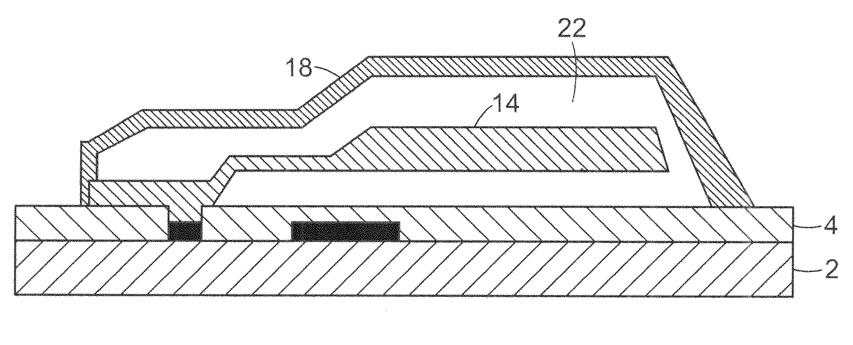
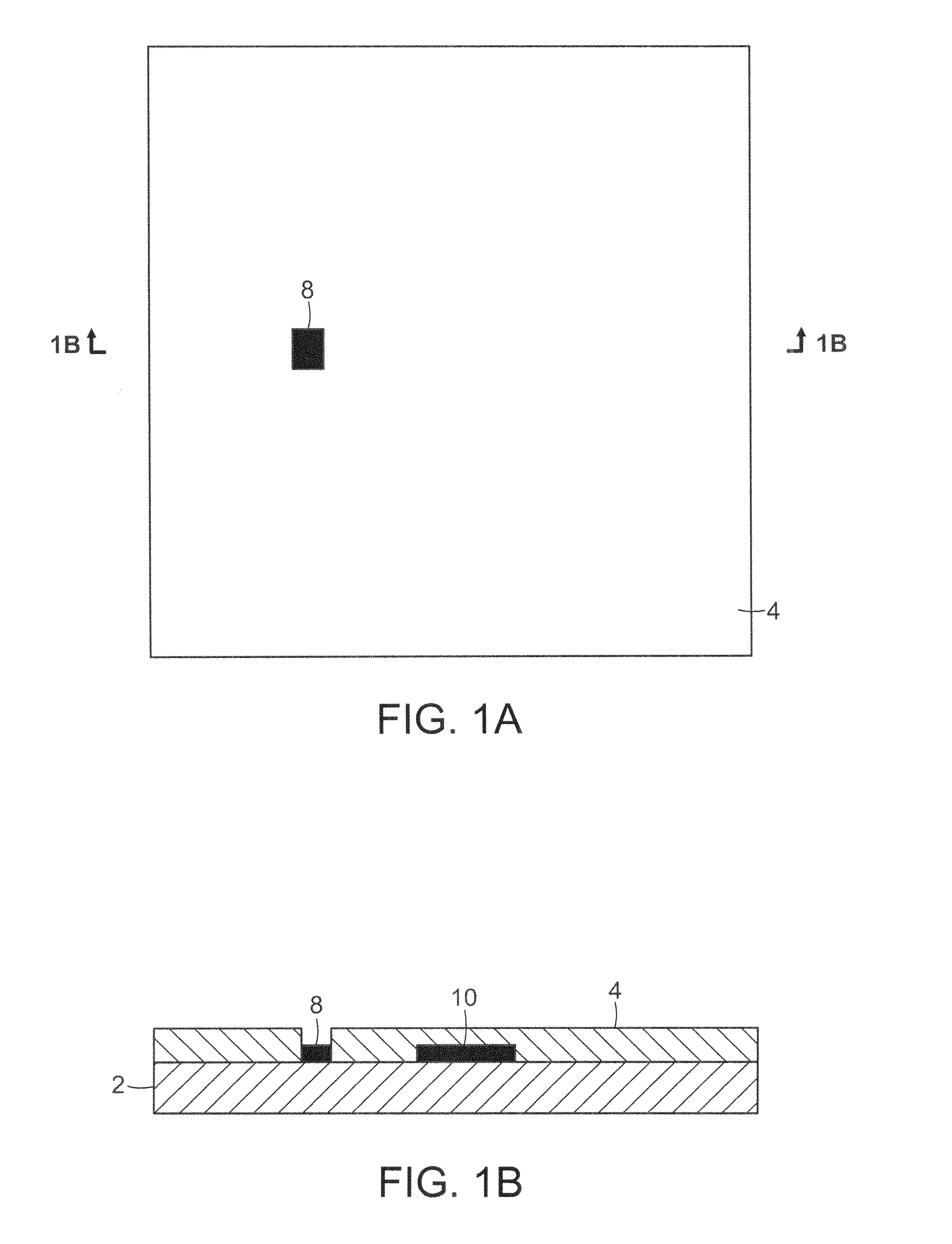
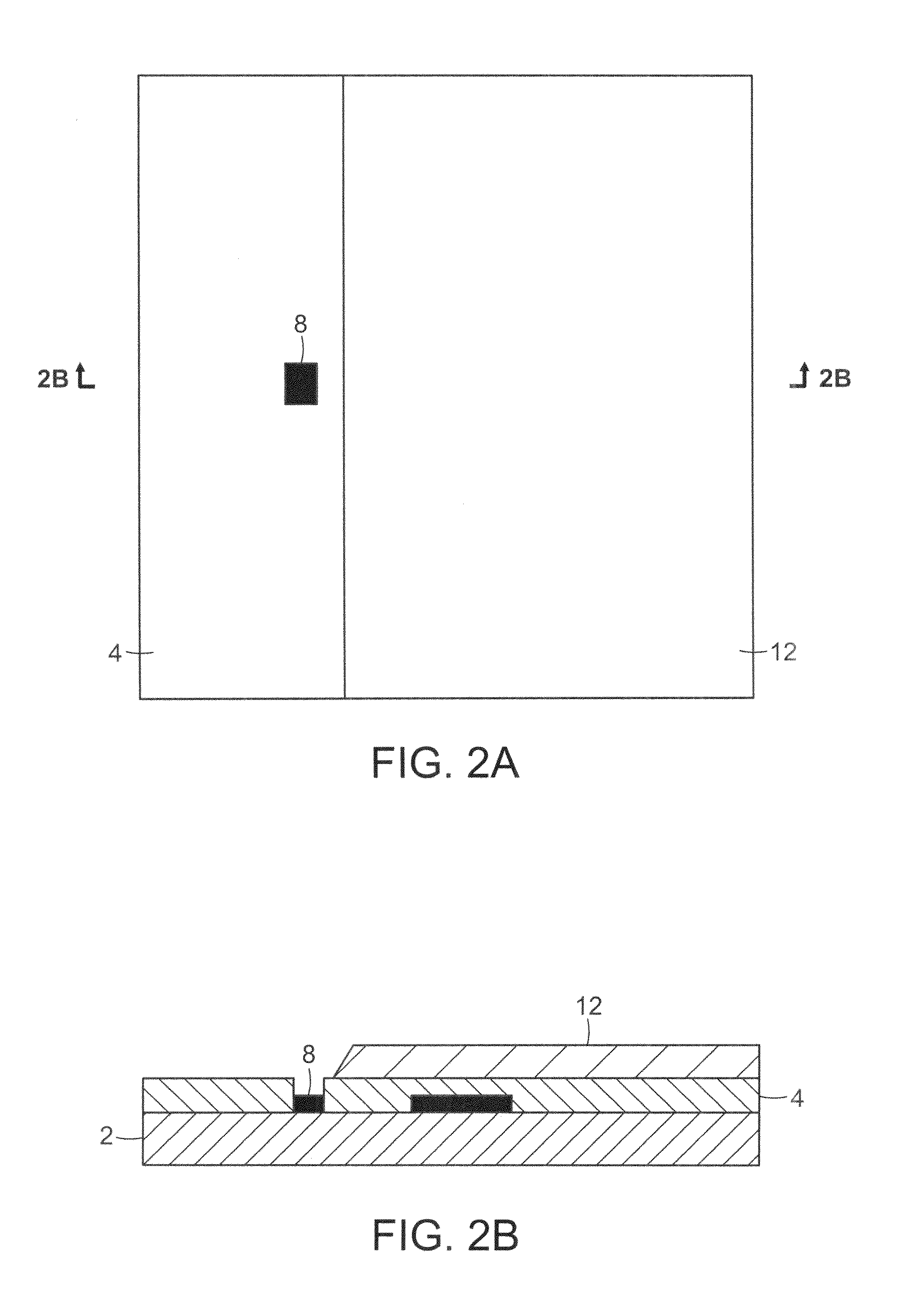
[0028]Disclosed herein are methods of creating high stiffness, high strength caps for the creation of cavities enclosing regions of interest on wafer surfaces and techniques to prevent formation of voids in the caps, where the caps are comprised of one or more high-stiffness materials, such as, for example, alumina, and are preferably deposited using a process designed to increase the rigidity and stiffness of the cap as well as its adhesion to the wafer surface.

[0029]In the present application, the term “high stiffness material” is henceforth defined to mean a material that is characterized by having a Young's modulus in excess of 80 GPa and which can be deposited in layers between 5 and 50 microns in thickness. Cap structures composed of or overlaid by one or more layers of a high stiffness material is preferably stiff enough to withstand a uniform pressure equivalent to up to about 60 atmospheres, with no portion of the cap structure deflecting by more than 1 micron from its init...


PUM


Abstract

This invention comprises a process for fabricating a micro mechanical structure in a sealed cavity having a multi-layer high stiffness cap. The high stiffness material used for the cap protects the underlying microstructure from destructive environmental forces inherent in the packaging process and from environmental damage.

Description

CROSS-REFERENCE TO RELATED APPLICATIONS[0001]This application claims the benefit of priority under 35 U.S.C. §120 from co-pending, commonly owned U.S. non-provisional patent application, Ser. No. 10 / 374,150, entitled “MICROMACHINED ASSEMBLY WITH A MULTI-LAYER CAP DEFINING A CAVITY,” filed on Feb. 25, 2003.FIELD OF THE INVENTION[0002]This invention relates to the field of integrated circuits that incorporate micro-electro-mechanical systems (MEMS) or other micro-mechanical devices, and, in particular, to the creation of sealed cavities for the encapsulation of said MEMS or micro-mechanical devices.BACKGROUND OF THE INVENTION[0003]It is known in the prior art to create sealed cavities on an integrated circuit wafer for a variety of applications, for example, as a pressure sensor or a microphone. It is also known to encapsulate movable micro-mechanical components on a wafer within a sealed cavity. The encapsulation of micro-mechanical structures in a sealed cavity is desirable for seve...

Claims


Application Information

Patent Timeline
IPC IPC(8): H01L31/058B81B7/02
CPCB81C1/00333B81B2207/015B81C2203/0136B81C2203/0145
Inventor CARLEY, L. RICHARD
Owner CYMATICS LAB CORP
Why Eureka
Try Eureka