
Focus/detector system of an x-ray apparatus for generating phase contrast recordings

a technology of x-ray apparatus and detector system, which is applied in the direction of instruments, diaphragms, applications for radiation diagnostics, etc., can solve the problems of cost-intensive installation and adjustment, and achieve the effects of simple structure, large absorption difference, and good stability

Inactive Publication Date: 2009-02-17
SIEMENS HEALTHCARE GMBH +1
View PDF22 Cites 78 Cited by
  • Summary
  • Abstract
  • Description
  • Claims
  • Application Information

AI Technical Summary

Benefits of technology

[0010]In this way, it is possible to use radiation sources which have extents that correspond to normal X-ray tubes in CT systems or transmitted-light X-ray systems so that, for example, even well-differentiated soft tissue tomographs can now be made in the field of general medical diagnosis with the aid of X-ray devices.
[0041]Another alternative embodiment may reside in the light sinks being arranged in cascade fashion and respectively including a filter on the scintillator side with a photodiode, which limits the frequencies on one side so that a reduced number of frequencies is measured in the subsequent filter / photodiode set. With this variant the photodiodes are thus arranged in cascade behind filters, the filters increasingly cutting off the frequencies beginning on one side of the frequency spectrum. In this way, a photodiode on the side facing toward the input side of the light can detect the entire frequency spectrum and a respectively further restricted spectrum can be measured at each further photodiode, so that the intensity of individual spectral ranges can be determined.

Problems solved by technology

A problem with this type of focus / detector combination is that on the one hand the analysis grating constitutes an additional sensitive component, which is cost-intensive to install and adjust.

Method used


Image

  • Focus/detector system of an x-ray apparatus for generating phase contrast recordings
  • Focus/detector system of an x-ray apparatus for generating phase contrast recordings
  • Focus/detector system of an x-ray apparatus for generating phase contrast recordings

Examples


Embodiment Construction

[0064]It will be understood that if an element or layer is referred to as being “on”, “against”, “connected to”, or “coupled to” another element or layer, then it can be directly on, against, connected or coupled to the other element or layer, or intervening elements or layers may be present. In contrast, if an element is referred to as being “directly on”, “directly connected to”, or “directly coupled to” another element or layer, then there are no intervening elements or layers present. Like numbers refer to like elements throughout. As used herein, the term “and / or” includes any and all combinations of one or more of the associated listed items.

[0065]Spatially relative terms, such as “beneath”, “below”, “lower”, “above”, “upper”, and the like, may be used herein for ease of description to describe one element or feature's relationship to another element(s) or feature(s) as illustrated in the figures. It will be understood that the spatially relative terms are intended to encompas...


PUM


Abstract

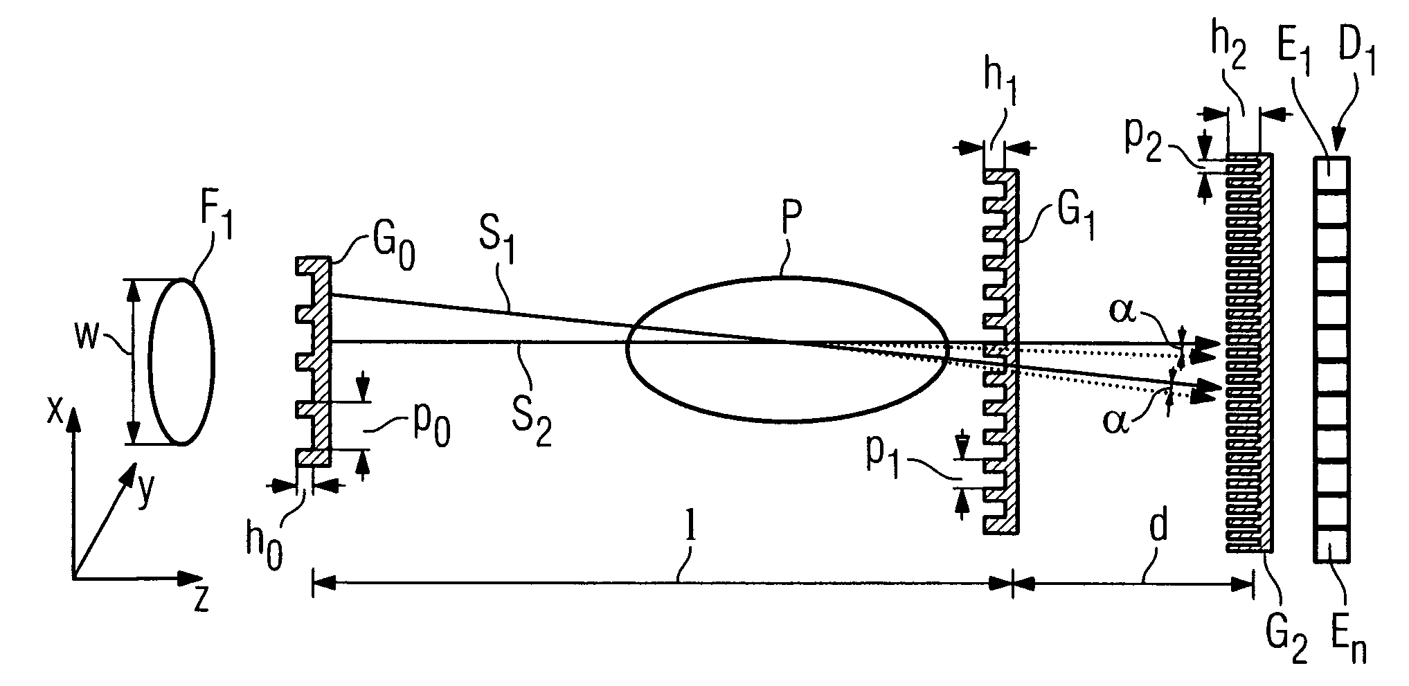
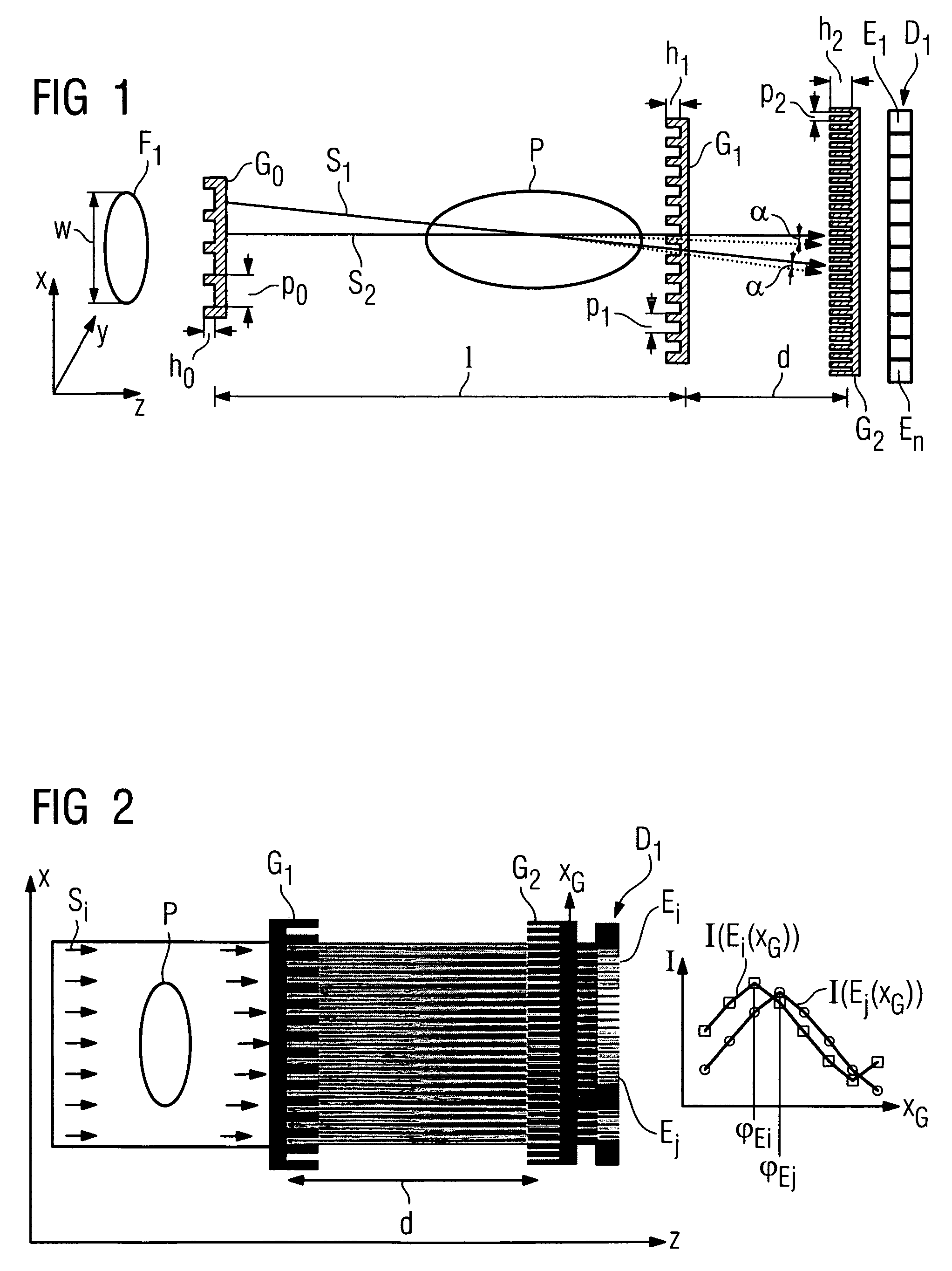
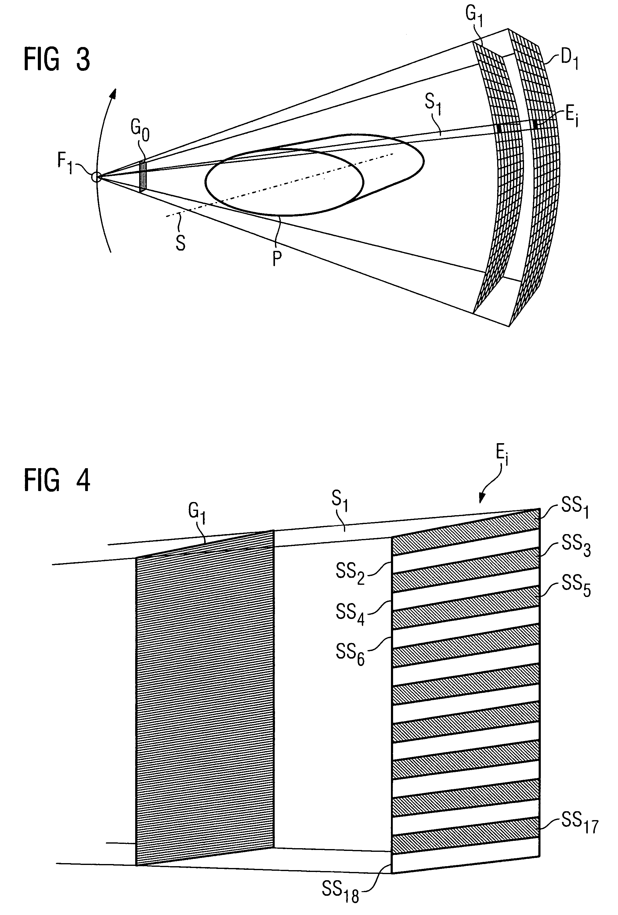
A focus / detector system of an X-ray apparatus and a method for generating projective or tomographic phase contrast recordings, are disclosed. In an embodiment of the system, the system includes a beam source equipped with a focus and a focus-side source grating, arranged in the beam path and generates a field of ray-wise coherent X-rays, a grating / detector arrangement having a phase grating and grating lines arranged parallel to the source grating for generating an interference pattern, and a detector having a multiplicity of detector elements arranged flat for measuring the position-dependent radiation intensity behind the phase grating. Finally, the detector elements are formed by a multiplicity of elongate scintillation strips, which are aligned parallel to the grating lines of the phase grating and have a small period, whose integer multiple corresponds to the average large period of the interference pattern which is formed by the phase grating.

Description

PRIORITY STATEMENT[0001]The present application hereby claims priority under 35 U.S.C. §119 on German patent application numbers DE 10 2006 004 976.4 filed Feb. 1, 2006, and DE 10 2006 017 291.4 filed Apr. 12, 2006, the entire contents of each of which is hereby incorporated herein by reference.FIELD[0002]Embodiments of the invention generally relate to a focus / detector system of an X-ray apparatus for generating projective and tomographic phase contrast recordings. For example, they may relate to one including a beam source having a focus, a detector arrangement for detecting the X-radiation and a set of X-ray optical gratings, for determining the phase shift when the X-radiation passes through a subject.BACKGROUND[0003]In computer tomography, tomographic recordings of a subject, in particular a patient, are generally made with the aid of absorption measurements of X-rays which pass through the subject, a radiation source generally being moved circularly or spirally around the subj...

Claims


Application Information

Patent Timeline
IPC IPC(8): G21K1/00G21K1/12
CPCA61B6/00A61B6/032A61B6/06A61B6/4233A61B6/4441A61B6/484G03B42/02G21K1/06A61B6/4291A61B6/4014A61B6/4266G21K2207/005A61B6/4028A61B6/4092
Inventor POPESCU, STEFANHEISMANN, BJORNHEMPEL, ECKHARDDAVID, CHRISTIANPFEIFFER, FRANZ
Owner SIEMENS HEALTHCARE GMBH
Learn More