Reduced-pressure drying apparatus

a drying apparatus and reducing pressure technology, applied in drying machines, lighting and heating apparatus, furniture, etc., can solve the problems of inability to secure the versatility of the apparatus, the film thickness in the plane is affected by the difference in drying rate, and the difficulty of drying liquid, so as to reduce the unevenness of the film thickness on the work surface, reduce the pressure, and reduce the effect of pressur

Inactive Publication Date: 2009-02-24
SEIKO EPSON CORP
View PDF7 Cites 20 Cited by
  • Summary
  • Abstract
  • Description
  • Claims
  • Application Information

AI Technical Summary

Benefits of technology

[0009]An advantage of the present invention is to provide a reduced-pressure drying apparatus in which the evaporation rate of a solvent contained in an applied liquid can be optimized in a drying process according a type of the liquid and the drying process under a reduced pressure can be carried out in an uniform distribution of the vapor pressure of the solvent.
[0010]According to an aspect of the invention, a reduced-pressure drying apparatus for drying a solvent in a liquid under a reduced pressure by evaporation of the solvent, includes a chamber including a first chamber and a second chamber, the first chamber accommodating work to which a liquid containing a film forming material is applied, the second chamber being coupled to the first chamber through a communicating part; a depressurizing unit depressurizing at least the second chamber; a communicating valve opening and closing the communicating part; and a control unit controlling a reduced pressure state at least of the second chamber by driving the depressurizing unit, the control unit also controlling an opening and closing state of the communicating part by driving the communicating valve.
[0011]The rheological properties of the liquid applied to the work differ depending on the kinds of the liquid. In some kinds of the liquid, the behavior of the liquid is affected in the course of the drying process when the vapor pressure and the evaporation rate sharply change due to depressurization. This results in unevenness in the thickness of the dried film. In order to dry the liquid such that the formed film after the drying is flat and the unevenness in the film thickness on the work surface becomes less, it is important to evaporate the solvent while preventing the liquid from flowing and being deformed in the course of drying. According to the aspect of the invention, the chamber is divided into the first chamber that accommodates the work and the second chamber whose pressure can be reduced by the depressurizing unit. The control unit can close the first chamber air-tightly and can communicate the first chamber with the second chamber by driving the communicating valve. Accordingly, if the first chamber is separated from the second chamber and air-tightly closed after the first chamber and the communicating second chamber are depressurized, the evaporation of the solvent is promoted in the first chamber, creating a pressure difference between the first chamber and the second chamber. Consequently, the evaporation rate of the solvent in the applied liquid can be made moderate corresponding to the reduced pressure state of the first chamber, and this can suppress the flow of the liquid. If the first chamber is made communicate with the second chamber after the pressure in the first room rises as the evaporation of the solvent progresses, the vapor of the solvent can be diffused into the second chamber because there is a pressure difference between the first chamber and the second chamber. The depressurizing unit then exhausts the solvent vapor diffused in the second chamber. In this way, the drying of the liquid is performed. The pressure in the first chamber will not be affected by the exhaustion of the depressurizing unit since the first chamber is air-tightly closed. Therefore, the unevenness in the evaporation rate of the solvent caused by the exhaustion flow can be reduced. This means that the evaporation rate of the solvent in the applied liquid can be optimized if the reduced pressure state of the first chamber is decided depending on the kinds of the liquid. Consequently, it is possible to provide the reduced pressure drying apparatus with which the depressurizing and drying can be carried out while keeping the vapor pressure distribution of the solvent substantially uniform. It is also possible to set appropriate depressurizing conditions according to the kinds of the liquid. This gives versatility to the reduced pressure drying apparatus.
[0012]In this case, the reduced-pressure drying apparatus may further include a pressure gauge measuring a reduced pressure state at least of the first chamber. The control unit drives the communicating valve to communicate the first chamber with the second chamber, and drives the depressurizing unit so that the first chamber and the second chamber are depressurized till a pressure value detected by the pressure gauge reaches a prescribed operational pressure. The control unit then drives the communicating valve to close the communicating part so that the first chamber is air-tightly closed. The control unit drives the communicating valve again to communicate the first chamber with the second chamber if the pressure value of the first chamber detected by the pressure gauge reaches a predetermined pressure value, and the control unit then drives the depressurizing unit to exhaust vapor of the solvent that is diffused in the first chamber and the second chamber.
[0013]The control unit firstly communicates the first chamber with the second chamber. After the depressurizing the chamber till the pressure value detected by the pressure gauge reaches a prescribed operational pressure, the first chamber is air-tightly closed. In this way, the solvent in the liquid which is applied to the work can be vaporized under the prescribed operational pressure in the first chamber without being affected by the exhaustion of the depressurizing unit. The first chamber is coupled again to the second chamber when the pressure gauge finds the pressure in the first chamber reach a predetermined pressure value. The vapor of the solvent flows and diffuses into the second chamber from the first chamber where the pressure becomes the predetermined pressure value. The control unit then makes the depressurizing unit exhaust the diffused vapor of the solvent. In this way, the liquid is dried under a reduced pressure. Since the first chamber is closed at the prescribed operational pressure, the evaporation rate of the solvent in the applied liquid can be controlled corresponding to the prescribed operational pressure. In addition, the unevenness in the evaporation rate of the solvent caused by the exhaustion flow can be reduced since it is not affected by the exhaustion of the depressurizing unit. This means that the evaporation rate of the solvent in the applied liquid can be optimized if the prescribed operational pressure in the first chamber is decided depending on the kinds of the liquid. Consequently, it is possible to provide the reduced pressure drying apparatus with which the depressurizing and drying can be carried out while keeping the vapor pressure distribution of the solvent substantially uniform.
[0014]In this case, the predetermined pressure value may be a sum of the prescribed operational pressure and a vapor pressure at which a certain amount of the solvent is evaporated in the air-tightly closed first chamber, and the control unit make the depressurizing unit exhaust the vapor of the solvent diffused in the first chamber and the second chamber under a pressure whose value is larger than the predetermined pressure value.

Problems solved by technology

However, in a drying process in which the liquid is dried to form the film, it is very difficult to dry the liquid so as to form the film having a completely uniform thickness throughout the film when it is under the formation on the surface of the work or after the formation, and even with the above-described reduced-pressure drying apparatus.
Furthermore, vapor concentration (or pressure) distribution differs from a center part to a peripheral part, resulting in the film thickness in-plane distribution caused by a difference in drying rate.
Moreover, if the drying apparatus has to be optimally redesigned according to kinds of the liquid material or a configuration of the work to which the liquid is applied, the versatility of the apparatus cannot be secured.
This results in unevenness in the thickness of the dried film.
In this case, it is difficult to control the flow of the liquid in the course of the depressurization.

Method used


Image

  • Reduced-pressure drying apparatus
  • Reduced-pressure drying apparatus
  • Reduced-pressure drying apparatus

Examples


first embodiment

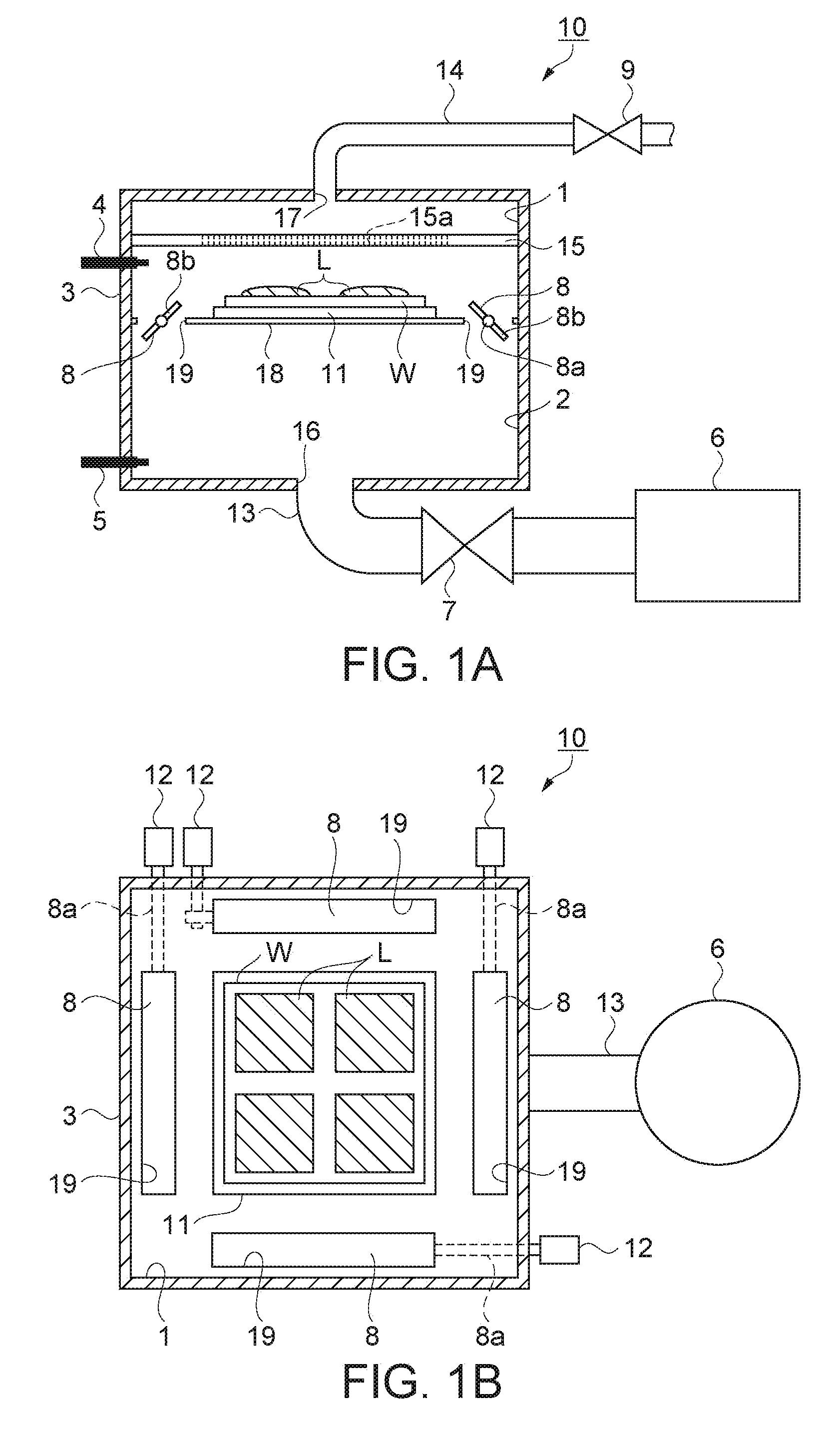
[0042]FIGS. 1A and 1B are schematic views showing a structure of a reduced-pressure drying apparatus according to a first embodiment of the invention. FIG. 1A is a perspective schematic view of the apparatus from the side to the inside of the apparatus. FIG. 1B is a perspective schematic view of the apparatus from the top side to the inside of the apparatus. As shown in FIG. 1A, a substrate W which is work to which liquid L is applied is provided in a chamber 3 of a reduced-pressure drying apparatus 10. The liquid L includes a film forming material that is an alignment film forming material in this embodiment. The reduced-pressure drying apparatus is equipment in which a solvent of the liquid L is evaporated and dried under a reduced pressure.

[0043]The chamber 3 includes a first chamber 1 which is illustrated in the upper side in FIG. 1A and a second chamber 2 which is illustrated in the lower side of the figure. A partition wall 18 divides the chamber 3 in such a way that the volum...

second embodiment

[0082]FIGS. 4A and 4B are schematic views showing a structure of a reduced-pressure drying apparatus according to a second embodiment of the invention. FIG. 4A is a perspective schematic view from the side to the inside of the apparatus. FIG. 4B is a perspective schematic view from the top side to the inside of the apparatus.

[0083]As shown in FIG. 4A, a reduced-pressure drying apparatus 30 has a chamber 33 and a vacuum pump 36. The chamber 33 includes a first chamber 31 and a second chamber 32 which is provided so as to surround the first chamber. The substrate W to which liquid L is applied is provided in the first chamber 31. The vacuum pump 36 can depressurize the second chamber 32.

[0084]The first chamber 31 is formed by parting the chamber 33 with a partition wall 48 which is provided in the bottom of the chamber 33 and has a box shape. A stage 41 on which the substrate W is placed is provided on the bottom of the first chamber 31. A communicating opening 49 whose size correspon...

third embodiment

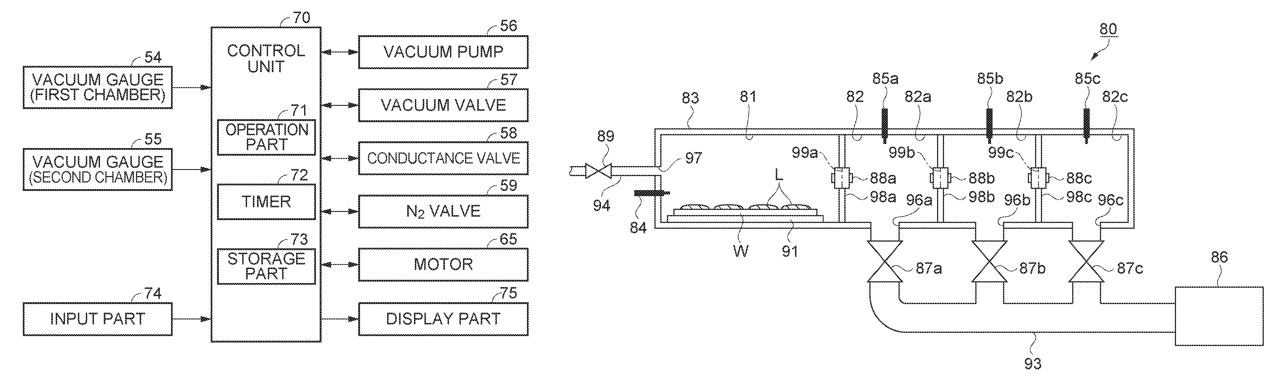
[0091]FIG. 5 is a schematic view showing a structure of a reduced-pressure drying apparatus according to a third embodiment of the invention. FIG. 5 is a perspective schematic view from the side to the inside of the apparatus.

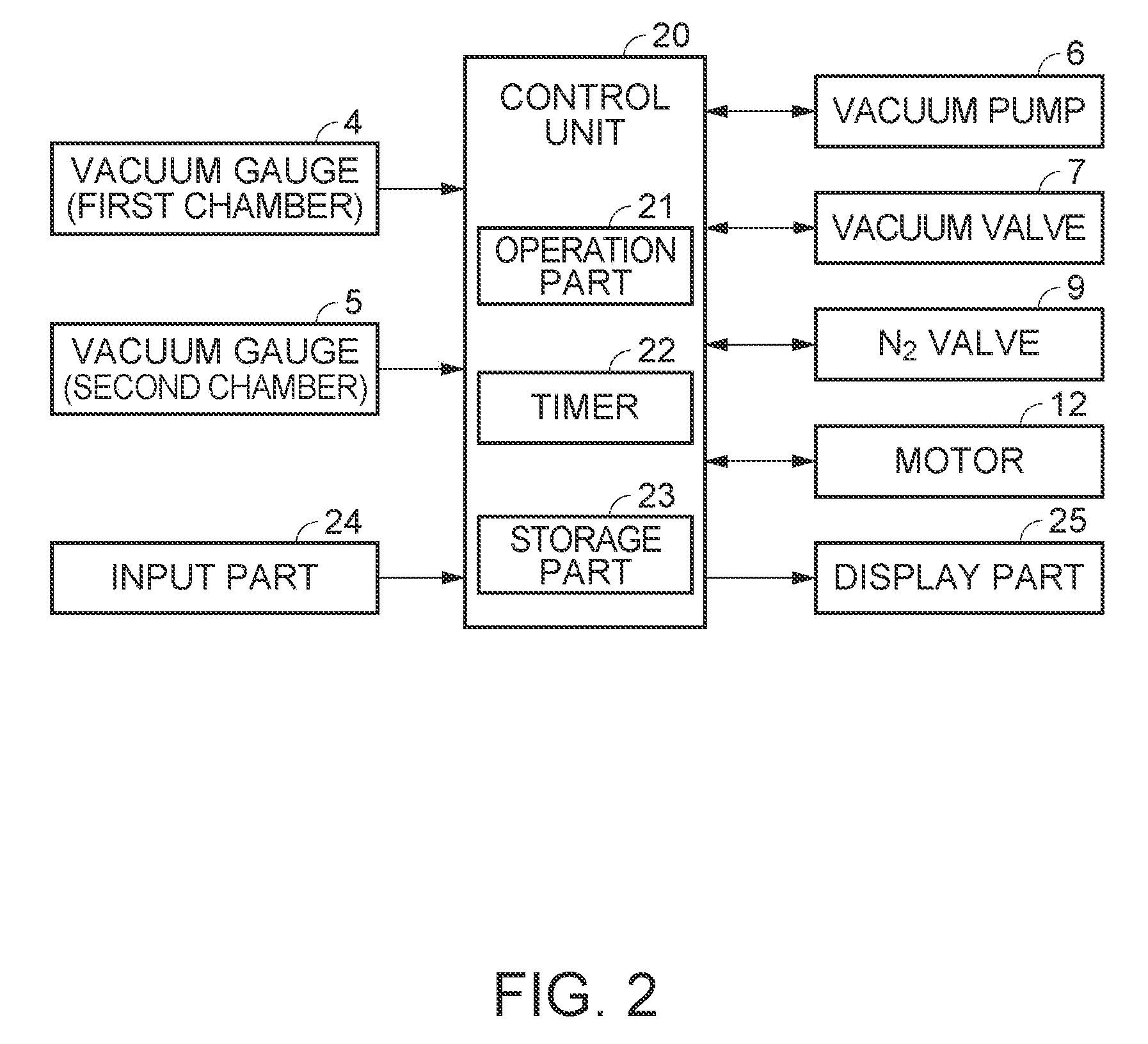
[0092]As shown in FIG. 5, a reduced-pressure drying apparatus 50 according to the third embodiment has a chamber 53, a vacuum pump 56 and a partition wall 68. The chamber 3 includes a first chamber 51 in which the substrate W to which the liquid L is applied is placed and a second chamber 52. The vacuum pump 56 can decrease the pressure in the second chamber 52. The partition wall 68 divides the chamber 3 into the first chamber 51 and the second chamber 52. The partition wall 68 is movable along the inner wall of the chamber 53. A vacuum gauge 54 which measures a pressure reducing state in the first chamber 51 and a vacuum gauge 55 which measures a pressure reducing state in the second chamber 52 are also provided.

[0093]A table 61 on which the substrate W is pl...


PUM


Abstract

A reduced-pressure drying apparatus for drying a solvent in a liquid under a reduced pressure by evaporation of the solvent, includes a chamber including a first chamber and a second chamber, the first chamber accommodating work to which a liquid containing a film forming material is applied, the second chamber being coupled to the first chamber through a communicating part; a depressurizing unit depressurizing at least the second chamber; a communicating valve opening and closing the communicating part; and a control unit controlling a reduced pressure state at least of the second chamber by driving the depressurizing unit, the control unit also controlling an opening and closing state of the communicating part by driving the communicating valve.

Description

BACKGROUND OF THE INVENTION[0001]1. Technical Field[0002]The present invention relates to a reduced-pressure drying apparatus that is used when work to which some liquid is applied is dried under reduced pressure so as to form a film on the surface of the work.[0003]2. Related Art[0004]A reduced-pressure drying apparatus in which a solvent component in a liquid is vaporized and dried out is used for forming a film on a wafer-like substrate such as a semiconductor substrate by applying the liquid containing a film formation material. JP-A-2002-313709 is an example of related art. The example proposed the reduced-pressure drying apparatus in which a substrate to which photoresist is applied is placed in a reduced-pressure chamber. A rectifying plate is provided so as to oppose the substrate and a venting hole is provided on the peripheral of the rectifying plate.[0005]The above-mentioned reduced-pressure drying apparatus exhausts from the upper part of the chamber and this forms a uni...

Claims


Application Information

Patent Timeline
Patent Type & Authority Patents(United States)
IPC IPC(8): F26B3/00
CPCF26B5/04
Inventor GOMI, KAZUHIRO
Owner SEIKO EPSON CORP
Why Eureka
Try Eureka