
Micromachined acoustic transducer and method of operating the same

a technology of acoustic transducer and micro-machine, which is applied in the direction of variable capacitor, fluid pressure measurement, instruments, etc., can solve the problems of device manufacturing and operation without obvious advantages, and difficulty in generating audible sound large enough for human hearing, etc., and achieves the effect of wide frequency rang

Inactive Publication Date: 2009-02-24
NEOMEMS TECH INC WUXI CHINA
View PDF8 Cites 21 Cited by
  • Summary
  • Abstract
  • Description
  • Claims
  • Application Information

AI Technical Summary

Benefits of technology

The solution enables efficient conversion of electrical energy to acoustic energy across a wide frequency range, including the audio range, with increased oscillating amplitude and reduced noise, allowing for adjustable sensitivity and scalable performance.

Problems solved by technology

The limit of membrane deflection in the linear range, which is usually on the order of sub-micron, makes it difficult to generate the audible sound that is large enough for human to hear.
The issue, however, is such a device has no obvious advantages in the manufacturing and operation compared with devices made with traditional technology.

Method used


Image

  • Micromachined acoustic transducer and method of operating the same
  • Micromachined acoustic transducer and method of operating the same
  • Micromachined acoustic transducer and method of operating the same

Examples


Embodiment Construction

)

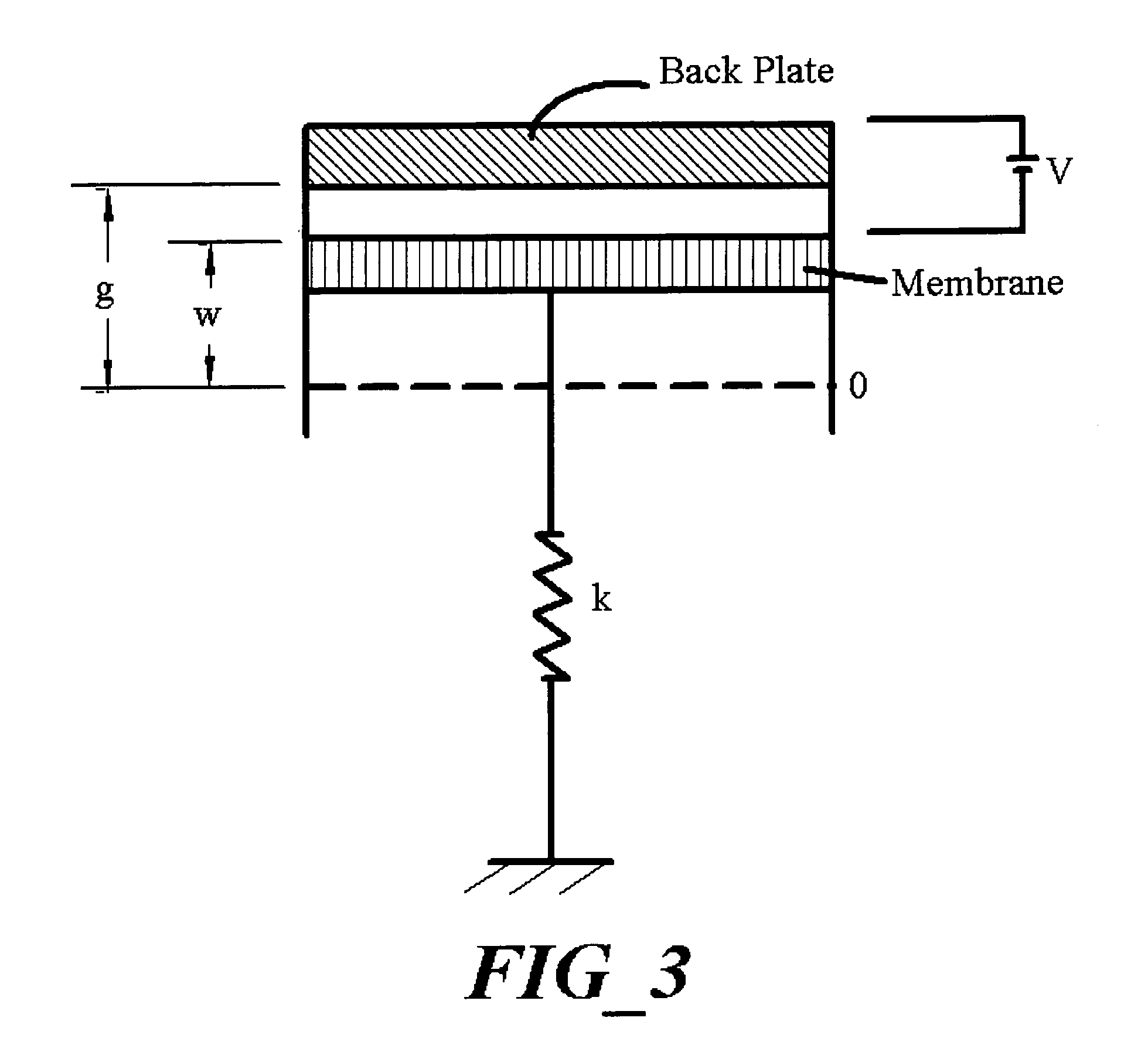
[0023]The classical model used to simulate the working of electrostatic microactuator is to consider a rigid membrane attached by a spring and subjected to an electrostatic field, as shown in FIG. 3. The mechanical law governing the electrostatic actuator can be expressed as follow:

[0024]m⁢ⅆ2⁢wⅆt2+λ⁢ⅆwⅆt+kw=ɛ⁢⁢V22⁢(g-w)2⁢S(1)

[0025]Where w is the deflection of membrane, m the mass, λ the damping factor, and k the spring constant. k depends on the geometry of the microstructure. The excitation is represented with the electrostatic pressure through a gap g applied on the membrane surface S, with V the bias voltage and ε the permittivity. The mass can be expressed with the geometrical characteristics of the plate: m=ρhS, with ρ the volume density and h the membrane thickness. Equation (1) shows clearly the non-linearity of the electrostatic microactuator. The excitation depends on the plate deflection. There is no analytic solution for this equation. We can express the solution of the ...


PUM

PropertyMeasurementUnit
frequencyaaaaaaaaaa
capacitanceaaaaaaaaaa
conductiveaaaaaaaaaa

Abstract

This invention relates generally to a micromachined acoustic transducer that has a scalable array of sealed cavities and perforated members forming capacitive cells that convert the electrical signal to acoustic signal or vice versa. It also relates to the method and more particularly to a micromachined acoustic transducer which includes a plurality of micromachined membranes and perforated members forming capacitive cells and more particularly to an acoustic transducer in which the capacitive cells are connected in a scalable array whereby electrical signals are applied to the said array and converted to acoustic signals. The transducer can either be used as an acoustic actuator or a microphone.

Description

CROSS REFERENCE TO RELATED APPLICATION[0001]U.S. Pat. Nos. 5,619,476; 5,870,351; 5,894,452; 6,493,288, and 6,552,469.BACKGROUND OF THE INVENTION[0002]Capacitive micromachined acoustic transducers have become more and more popular in today's sensor world. The efforts, however, have been mainly focused on the making of micromachined acoustic transducers to sense the passing acoustic signal. In other words, they are mainly used as microphones. There are also some efforts to develop the micromachined ultrasonic transducers which operate in the MHz or even higher frequency ranges. For example, U.S. Pat. Nos. 5,619,476; 5,870,351; 5,894,452, and 6,493,288 incorporated herein by reference, describe the fabrication of capacitive-type ultrasonic transducers in which membranes are supported above a substrate by insulative supports such as silicon nitride, silicon oxide and polyamide. The supports engage the edges of each membrane. A voltage applied between the substrate and a conductive film ...

Claims


Application Information

Patent Timeline
Patent Type & Authority Patents(United States)
IPC IPC(8): G01L9/12
CPCH04R19/00
Inventor WANG, YUNLONG
Owner NEOMEMS TECH INC WUXI CHINA
Learn More