In situ determination of pixel mapping in interferometry
a technology of interferometry and in situ determination, applied in the field of interferometry, can solve the problems of zernike decomposition, wavefront generator, pixel coordinates, wavefront generators used for illuminating and imaging the part, and usually introduce a significant amount of distortion
- Summary
- Abstract
- Description
- Claims
- Application Information
AI Technical Summary
Benefits of technology
Problems solved by technology
Method used
Image
Examples
example a
Spherical Cavity, z-Motion Only
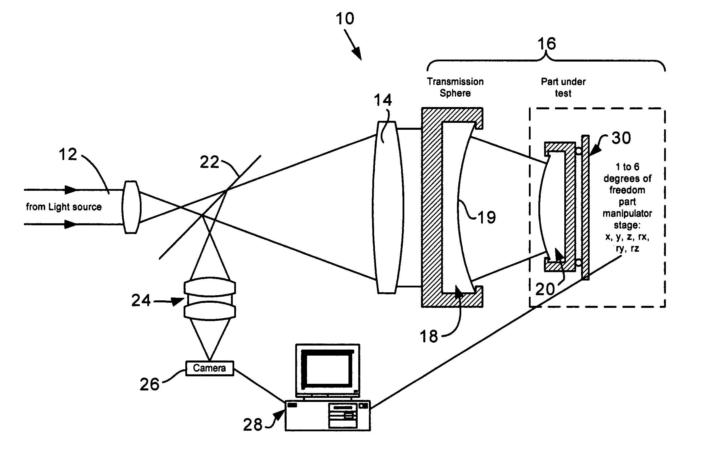
[0026]In principle, the method can be applied to many kinds of interferometers such as Fizeau-Interferometers, Mirau-Interferometers, Twyman-Green-Interferometers, Michelson-Interferometers, Linnik-Interferometers, Grazing incidence interferometers, Shearing interferometers, and so forth. In the following, a first version of the method is described using the special case of a Fizeau-interferometer. The Fizeau case is the easiest case because there are no additional optics between the reference and the object surface in a Fizeau configuration. Because of this, the Fizeau type is probably the most widely used interferometer in the optics industry.
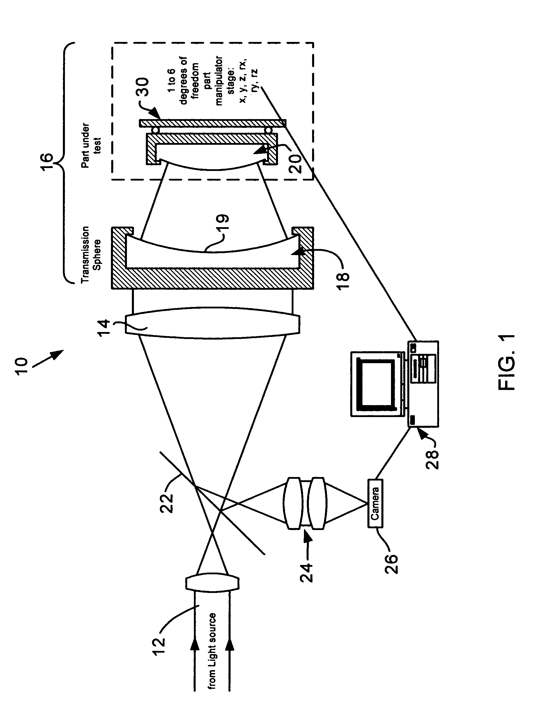
[0027]In FIG. 1, a typical Fizeau setup is shown generally designated at 10. A beam 12 coming from a light source is expanded by a collimation system 14 and then illuminates a spherical Fizeau cavity 16. The light is partially reflected at the last surface 19 of element comprising a transmission sphere 18 (which...
example b
Spherical Cavity, x,y-Motion Only
[0039]Example A described the simplest case using an axial motion along only the system axis and described the basic idea of the method. It is obvious that measuring cos u and then calculating sin u is not a good measurement when u becomes small, that is, for pixels close to the optical axis. Here u only enters the equations quadratically. For a good measurement, a linear relationship would be preferable.
[0040]This is easily achieved by displacing the part laterally in two degrees of freedom, namely once along the x-axis using the displacement δx, and a second time using a y-displacement of δy.
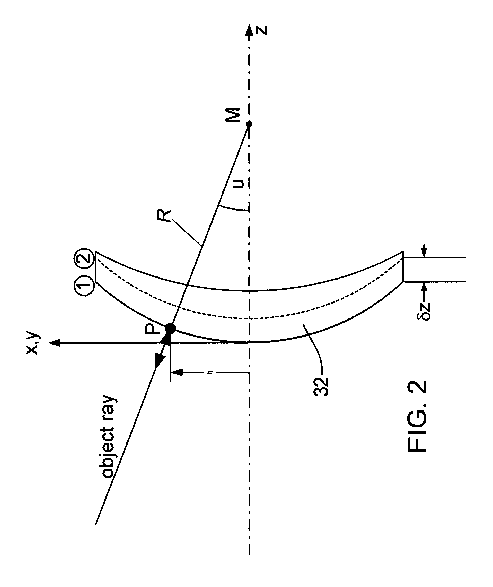
[0041]In this, the change in phase is with good approximation described as the scalar product between the probe motion (x or y, respectively) and the probe ray under consideration. Please refer again to FIG. 2. For the coordinates shown in the FIG. 2, this means that the phase difference with respect to the base position is given by:
DX=δx sin u cos θ
DY=δy sin u...
example c
Spherical Cavity, x,y,z-Motion
[0053]In principle, the approach described under Example B is sufficient to get the coordinates on a part if the manipulator commands (x,y)-motions precisely. In the following, a refinement of the method that is important for practical reasons is discussed.
[0054]Consider again a spherical cavity, but this time with a manipulator capable of manipulating the x, y, and z-degrees of freedom. Here, the following relationships hold:
DX=δ x sin u cos θ
DY=δ y sin u sin θ
DZ=δ z cos u (Eq. 7)
[0055]The instrument measures the phase map differences DX, DY and DZ, and the manipulator reports back measured displacements δx, δy and δz. This is true in principle but, in practice, the manipulator cannot usually provide a pure x-shift, a pure y-shift or a pure z-shift with ultimate perfection. If a pure x-shift is commanded, for example, there may still be small motion components in the y- and z-direction as well.
[0056]Now consider the case where the external feedback fr...
PUM
 Abstract
Description
Claims
Application Information
 - R&D
- Intellectual Property
- Life Sciences
- Materials
- Tech Scout
- Unparalleled Data Quality
- Higher Quality Content
- 60% Fewer Hallucinations
Browse by: Latest US Patents, China's latest patents, Technical Efficacy Thesaurus, Application Domain, Technology Topic, Popular Technical Reports.
© 2025 PatSnap. All rights reserved.Legal|Privacy policy|Modern Slavery Act Transparency Statement|Sitemap|About US| Contact US: help@patsnap.com


