Cooling system for vehicle

a technology for cooling systems and vehicles, applied in vehicle components, superstructure sub-units, propulsion parts, etc., can solve problems such as difficulty in improving the heat radiation capacity of radiators, and achieve the effect of reducing the air pressure in the ventilation du

Inactive Publication Date: 2009-03-03
DENSO CORP +1
View PDF8 Cites 29 Cited by
  • Summary
  • Abstract
  • Description
  • Claims
  • Application Information

AI Technical Summary

Benefits of technology

[0004]In view of the above-described problem, it is an object of the present invention to improve the cooling capacity of a cooling system by using a simple structure.
[0006]Accordingly, a speed of air flowing near the outlet can be made faster than that flowing away from the outlet, and a pressure of air flowing near the outlet decreases. Therefore, air in the ventilation duct is drawn to a neighborhood of the low-pressure outlet and discharged to an exterior of the ventilation duct. In this case, because cooling air including the traveling wind supplied to the heat exchanger can be effectively increased, heat radiation capacity of the heat exchanger, that is, cooling capacity of the cooling system can also be improved.
[0007]According to another aspect of the present invention, the edge portion defining the outlet is provided at a bottom side of the wall, and a bottom end of the wall on a vehicle front side is positioned lower than a bottom end of the wall on a vehicle rear side. In this case, the opening direction of the outlet can be readily set to lean to the vehicle rear side from the vertical direction.
[0008]For example, the wall is arranged to increase a flow speed of air around the outlet. That is, a speed increasing portion can be provided in the ventilation duct. Alternatively, the wall is arranged to reduce a pressure of air flowing around the outlet. That is, a pressure reducing portion can be provided in the ventilation duct. In this case, the air amount passing through the heat exchanger can be effectively increased.
[0010]Further, the ventilation duct has a communication hole at a position upstream from the blower in the air flow, and an interior of the ventilation duct communicates with an exterior of the ventilation duct through the communication hole. In this case, even when a large amount of air flows into the ventilation duct in a high-speed vehicle traveling, air can be readily discharged also through the communication hole, and air pressure in the ventilation duct can be reduced. The communication hole can be closed when the blower is operated.

Problems solved by technology

However, it is difficult to improve a heat radiation capacity of the radiator, that is, a cooling capacity of the cooling system by using a simple structure.

Method used


Image

  • Cooling system for vehicle
  • Cooling system for vehicle
  • Cooling system for vehicle

Examples


first embodiment

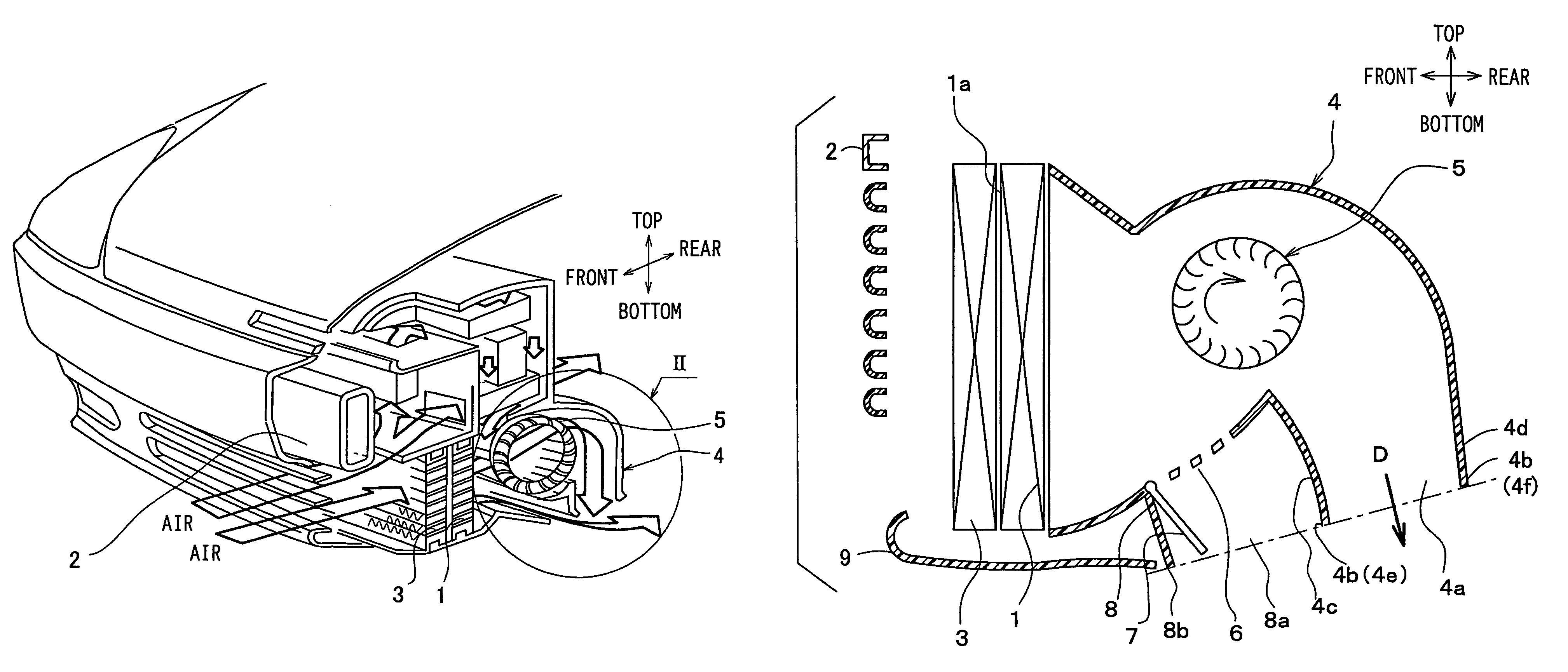
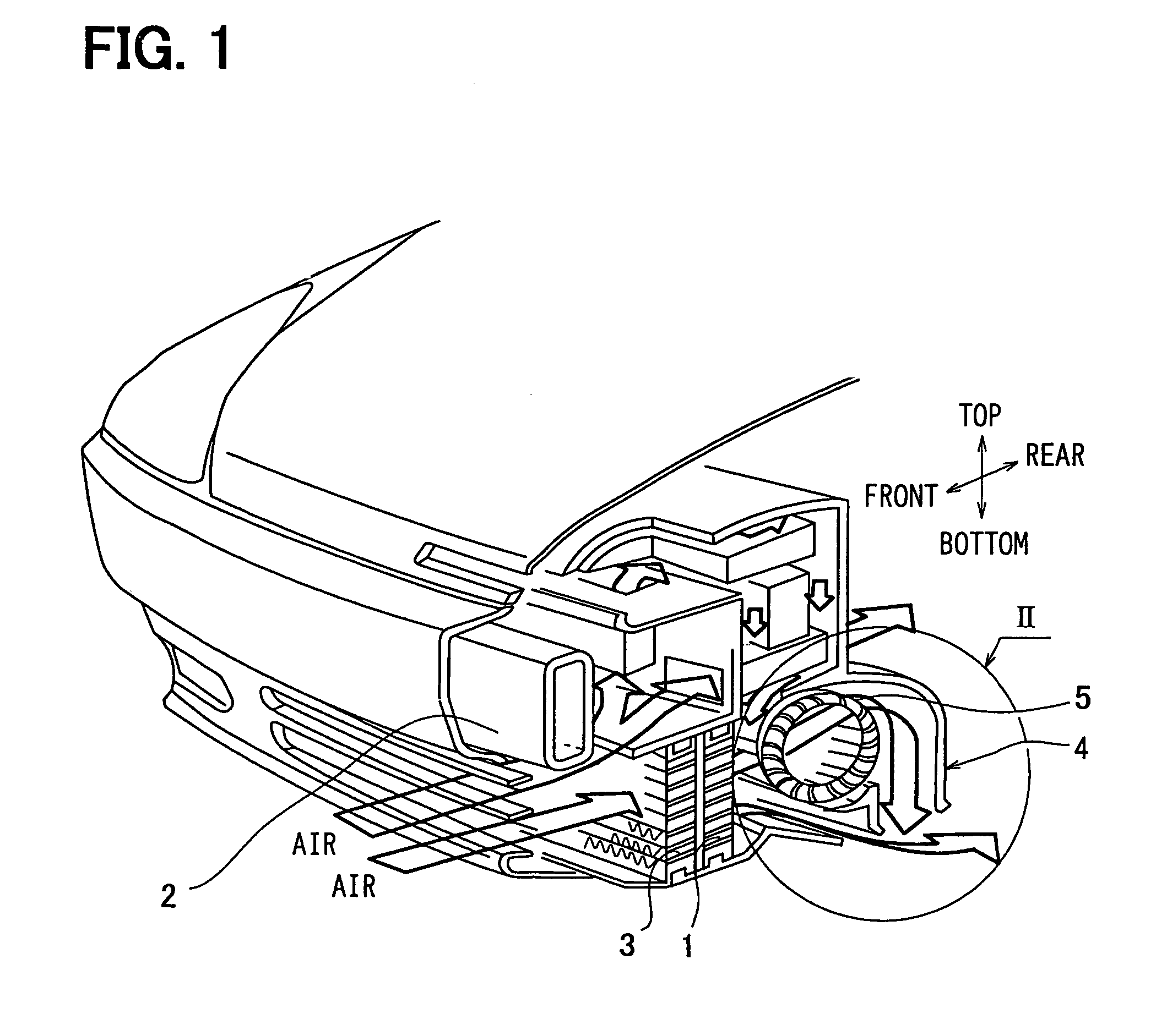
[0016]The first embodiment of the present invention will be now described with reference to FIGS. 1-3.

[0017]In FIG. 1, a radiator 1 is a heat exchanger for radiating heat, which cools engine-cooling water by exchanging heat between the outside air and the engine-cooling water which has cooled an engine (an internal-combustion engine). The engine is used in a vehicle as a driving source for traveling.

[0018]In this embodiment, among the external size of the radiator 1, a dimension parallel to a vehicle width is made larger than a dimension parallel to a vehicle height direction. Therefore, the height dimension of the radiator 1 is shortened to make the radiator 1 flat while a sufficient heat radiation capacity of the radiator 1 is maintained. Then, the radiator 1 is disposed in the vehicle, such that the whole radiator 1 is positioned lower than a bumper reinforcement member 2 when viewed from a vehicle front.

[0019]The bumper reinforcement member 2 lies in a vehicle front end portion ...

second embodiment

[0045]In this embodiment, an axis-flow fan (referring to JIS B 0132 No.1012) is used as the blower 5, where air passes through the fan in its axis direction. In the second embodiment, the other parts are similar to those of the above-described first embodiment.

Other Embodiments

[0046]Although the present invention has been fully described in connection with the preferred embodiments thereof with reference to the accompanying drawings, it is to be noted that various changes and modifications will become apparent to those skilled in the art.

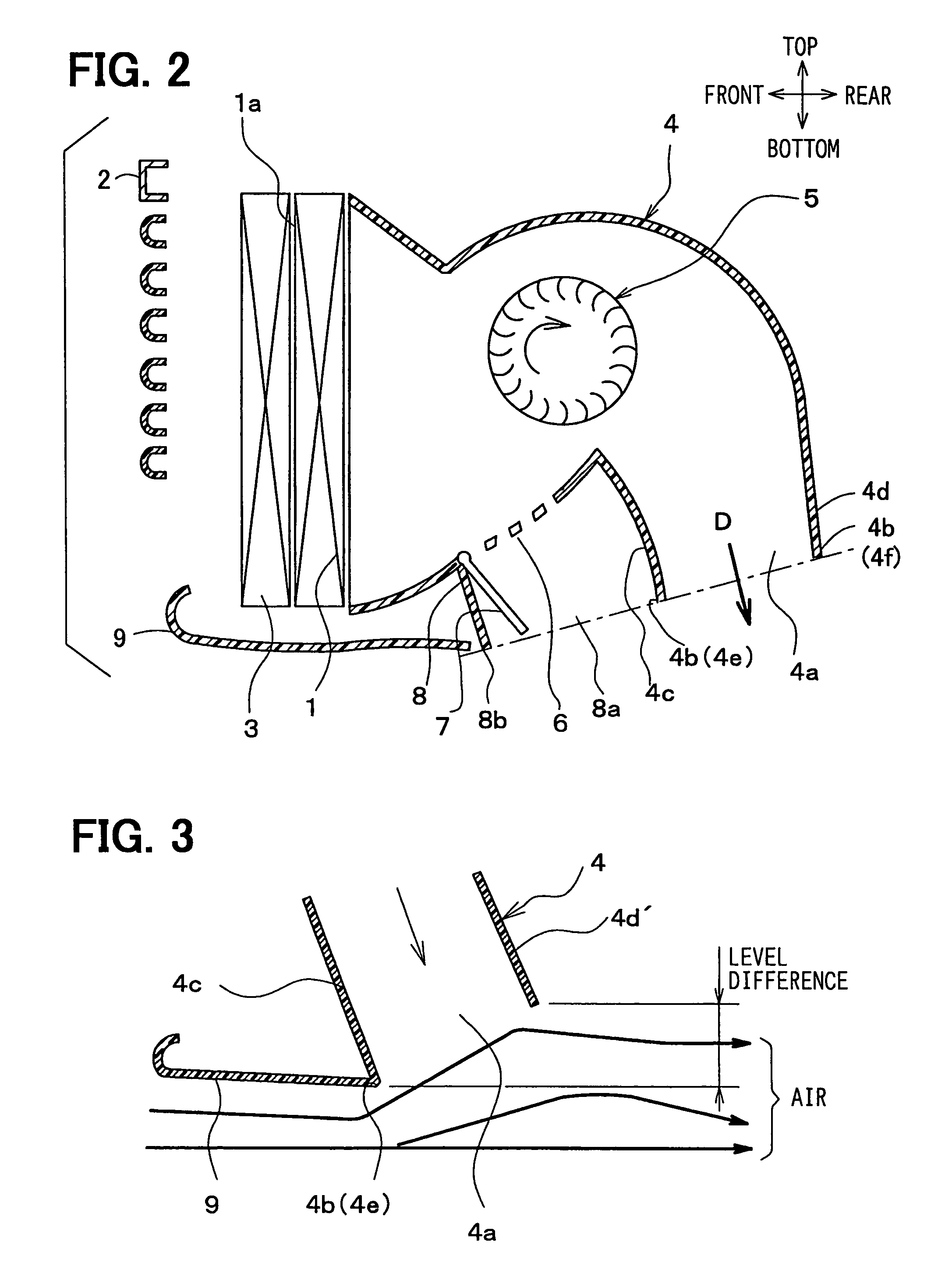
[0047]For example, each of the outlet 4a and the outlet 8a can also be constructed with an upward or sideward opening, without being limited to the above-described embodiments where each of the outlet 4a and the outlet 8 is constructed with a downward opening.

[0048]In the above-described embodiments, a heat-exchange core surface 1a of the radiator 1 is arranged in the vehicle nearly parallel to the vertical direction. However, the present invention ...


PUM


Abstract

In a ventilation duct of a cooling system, a level difference is formed between a wall located on a vehicle front side and a wall located on a vehicle rear side because a bottom end of the wall located on the vehicle front side is lower than a bottom end of the wall located on the vehicle rear side. The level difference makes a speed of a traveling wind flowing near an outlet faster than that flowing away from the outlet. Therefore, a pressure of the traveling wind flowing near the outlet decreases. As a result, air flows in the ventilation duct to be drawn to the neighborhood of the low-pressure outlet, and discharged out. Because cooling air including the traveling wind can be increased, heat radiation capacity of a radiator disposed in the ventilation duct is improved, and the cooling capacity of the cooling system can also be improved.

Description

CROSS REFERENCE TO RELATED APPLICATION[0001]This application is based on Japanese Patent Application No. 2003-279191 filed on Jul. 24, 2003, the disclosure of which are incorporated herein by reference.FIELD OF THE INVENTION[0002]The present invention relates to a cooling system for a vehicle. The cooling system is suitably used for a vehicle driving source for traveling, such as an internal combustion engine (engine) and an electric motor including a motor driving circuit.BACKGROUND OF THE INVENTION[0003]A cooling system for a vehicle supplies a traveling wind or a cooling air blown by a blower to a radiator. However, it is difficult to improve a heat radiation capacity of the radiator, that is, a cooling capacity of the cooling system by using a simple structure.SUMMARY OF THE INVENTION[0004]In view of the above-described problem, it is an object of the present invention to improve the cooling capacity of a cooling system by using a simple structure.[0005]According to an aspect of...

Claims


Application Information

Patent Timeline
Patent Type & Authority Patents(United States)
IPC IPC(8): B60K11/04B62D25/08B60K11/02
CPCB60K11/02B60K11/04
Inventor KUNIKATA, YUHEIMAEDA, AKIHIROSUGIYAMA, TOSHIKIHOSHI, JUN
Owner DENSO CORP
Why Eureka
Try Eureka