Portable air separation/air dehydration system

a technology of air separation and air dehydration system, which is applied in the field of separation of air into components, can solve the problems of not being portable, expensive and inconvenient to set up and dismantle an air separation system repeatedly, and achieve the effect of simplifying the process of providing and reducing costs

Active Publication Date: 2009-03-03
GENERON IGS
View PDF14 Cites 35 Cited by
  • Summary
  • Abstract
  • Description
  • Claims
  • Application Information

AI Technical Summary

Benefits of technology

[0010]The present invention comprises an air separation system that is carried on a truck or equivalent vehicle. At a minimum, the air separation system includes a feed compressor and a gas separation membrane, the membrane being connected to receive compressed air from the feed compressor, and to separate the air into components. The feed compressor receives power from the engine of the vehicle, but only when the vehicle is not moving under its own power. The engine of the vehicle is connected, through appropriate linkages, either to the drive shaft of the vehicle or to the compressor, but not to both at the same time. Also, heat from the vehicle engine may be used to heat the compressed air, prior to its passage through the membrane, to prevent the formation of water due to condensation.
[0015]The invention therefore includes the method of using the air separation / air dehydration system at one location, disconnecting that system, driving the vehicle to another location, and connecting the engine to the compressor(s) so as to operate the system at the new location. Since the air separation / air dehydration system is entirely disposed on the vehicle, it can be quickly and easily moved from one location to another. The invention is particularly useful in well operations where the air separation or air dehydration system is used for fewer than 24 hours at any one site.
[0022]The invention has the further object of providing a method of operating an air separation or air dehydration system for short times, in multiple locations.
[0023]The invention has the further object of simplifying the process of providing air separation or air dehydration services for relatively brief times at multiple locations.
[0024]The invention has the further object of reducing the cost of providing air separation or air dehydration services for relatively brief times at multiple locations.

Problems solved by technology

Membrane units of the prior art do have the disadvantage that they are not portable, and must be set up at each location where air separation is necessary.
It is expensive and inconvenient to set up and dismantle an air separation system repeatedly, for a plurality of oil drilling sites.
However, the system described in the cited patent uses a membrane system only to provide modified air to affect engine performance.
It does not, in itself, address the problem of the non-portability of air separation systems.

Method used


Image

  • Portable air separation/air dehydration system
  • Portable air separation/air dehydration system
  • Portable air separation/air dehydration system

Examples


Embodiment Construction

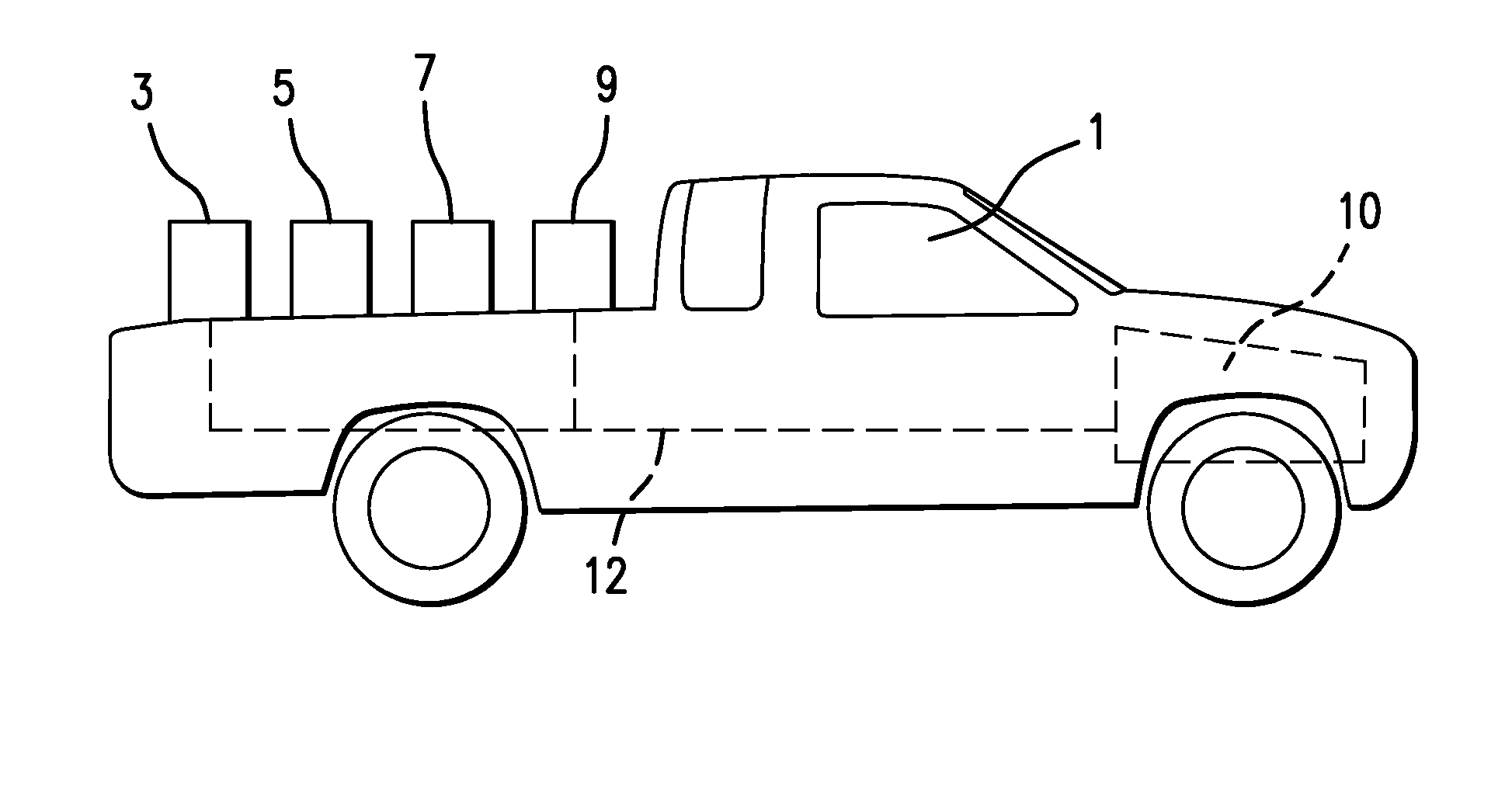
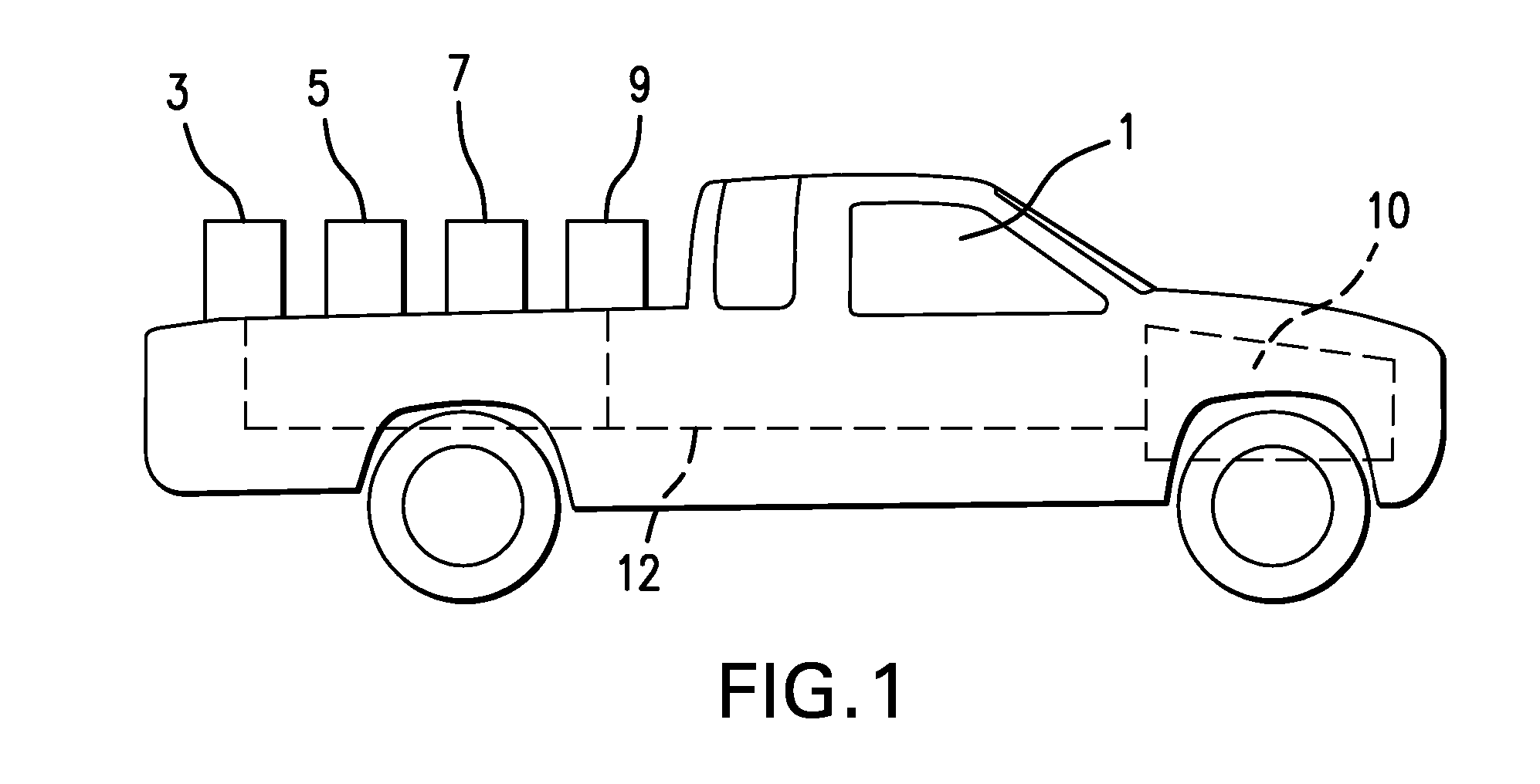
[0031]FIG. 1 shows a truck 1 which carries the components of a membrane-based air separation system. In the embodiment shown, the air separation system includes feed compressor 3, moisture separator 5, and membrane unit 7. Depending on the intended use of the air separation system, a booster compressor 9 may also be present. It is understood that still other components, such as those shown in U.S. Pat. No. 4,881,953, and described above, could be included on the truck bed. These other components could be filters, heaters, moisture traps, or other devices.

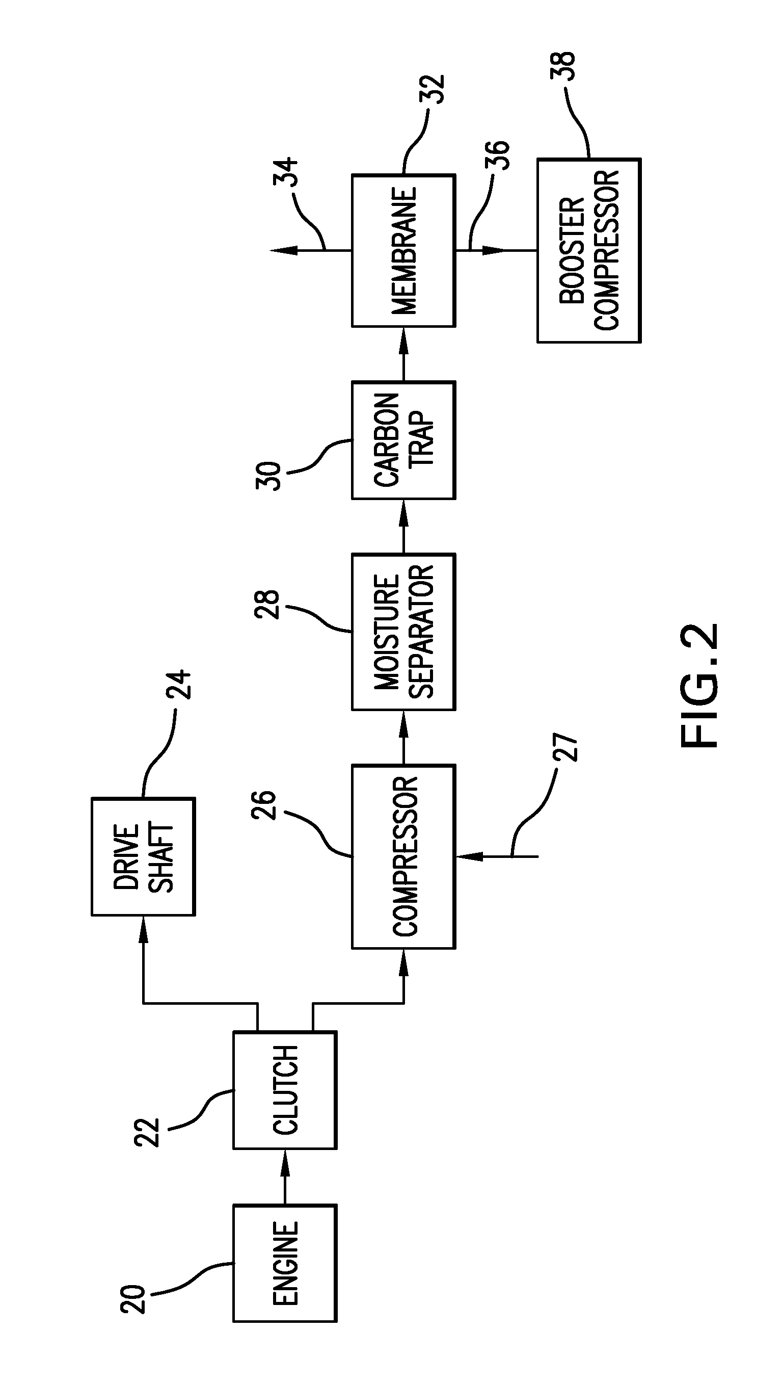
[0032]The truck has an engine 10 which is operatively connected to the feed compressor 3, as indicated by dotted line 12. In particular, the gear shift system of the truck is modified such that, in a first position, the engine is connected to the drive shaft, and in a second position, the engine is connected to operate the feed compressor. When the truck is in motion under its own power, the air separation system is not used, but is...


PUM

PropertyMeasurementUnit
pressuresaaaaaaaaaa
pressureaaaaaaaaaa
pressureaaaaaaaaaa

Abstract

A portable system for air separation or air dehydration, or both, is carried on a truck or equivalent vehicle. The air separation system includes, at a minimum, a feed compressor and a gas separation membrane. The air dehydration system includes a feed compressor and an air dehydration membrane. The feed compressor receives power from the engine of the vehicle, only when the vehicle is not moving under its own power. Heat from the vehicle engine may also be used to heat the compressed air stream to prevent the formation of water. The system can also be used to perform air dehydration and air separation simultaneously. The system is substantially self-contained, and can be easily driven from one location to another, simply by driving the vehicle to another location. The invention is especially useful in providing air separation or air dehydration services, or both, for relatively brief periods, at multiple locations.

Description

CROSS-REFERENCE TO PRIOR APPLICATION[0001]Priority is claimed from U.S. provisional patent application Ser. No. 60 / 672,899, filed Apr. 19, 2005, the disclosure of which is incorporated by reference herein.BACKGROUND OF THE INVENTION[0002]This invention relates to the field of separation of air into components by non-cryogenic means. The invention provides a portable, membrane-based air system, which can be used for air separation, air dehydration, or both. The system of the present invention can be easily moved from one location to another.[0003]The use of polymeric membranes to separate air into components has been known for a long time. An example of a membrane-based air separation system is given in U.S. Pat. No. 4,881,953, the disclosure of which is incorporated by reference herein. A polymeric membrane used for air separation is chosen to exhibit selectivity between oxygen and nitrogen. That is, the membrane tends to pass one component, designated the more “permeable” component...

Claims


Application Information

Patent Timeline
Patent Type & Authority Patents(United States)
IPC IPC(8): B01D53/22
CPCB01D53/22B01D63/00C01B13/0251B01D2313/22C01B2210/0046C01B2210/0062Y10S55/17B01D2313/221
Inventor JEFFERS, THOMAS J.NEWTON, DONALD E.TROIANO, TONY
Owner GENERON IGS
Why Eureka
Try Eureka