Deflecting electromagnet and ion beam irradiating apparatus
a technology of ion beam and electromagnet, which is applied in the direction of beam deviation/focusing, separation process, instruments, etc., can solve the problems of difficult supply from the outside, difficult to efficiently transport ion beam, complex structure, etc., and achieves efficient neutralization, simplified power source configuration, and wide space charge of ion beam
- Summary
- Abstract
- Description
- Claims
- Application Information
AI Technical Summary
Benefits of technology
Problems solved by technology
Method used
Image
Examples
first embodiment
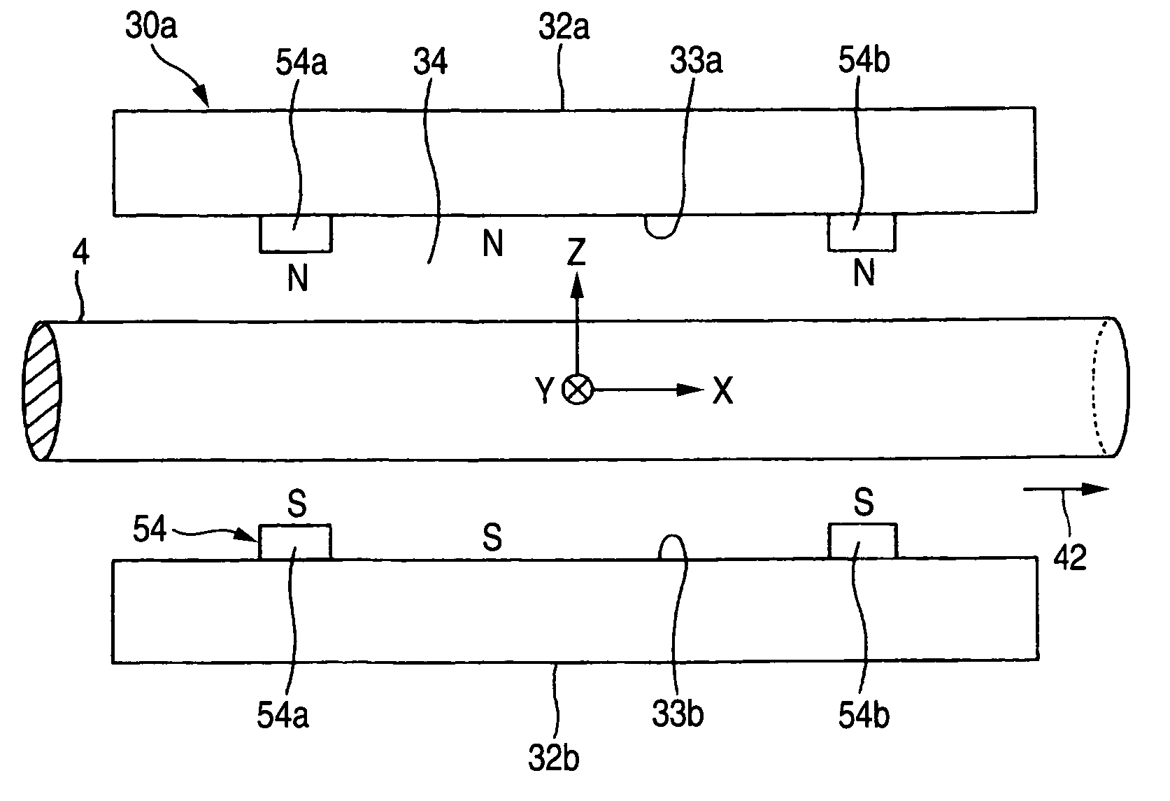
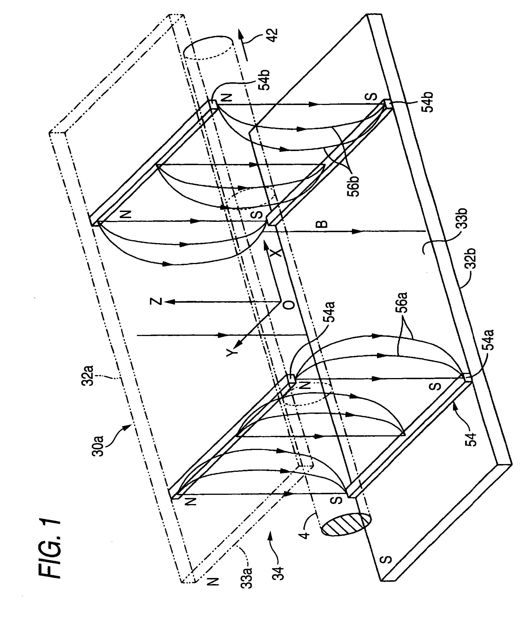
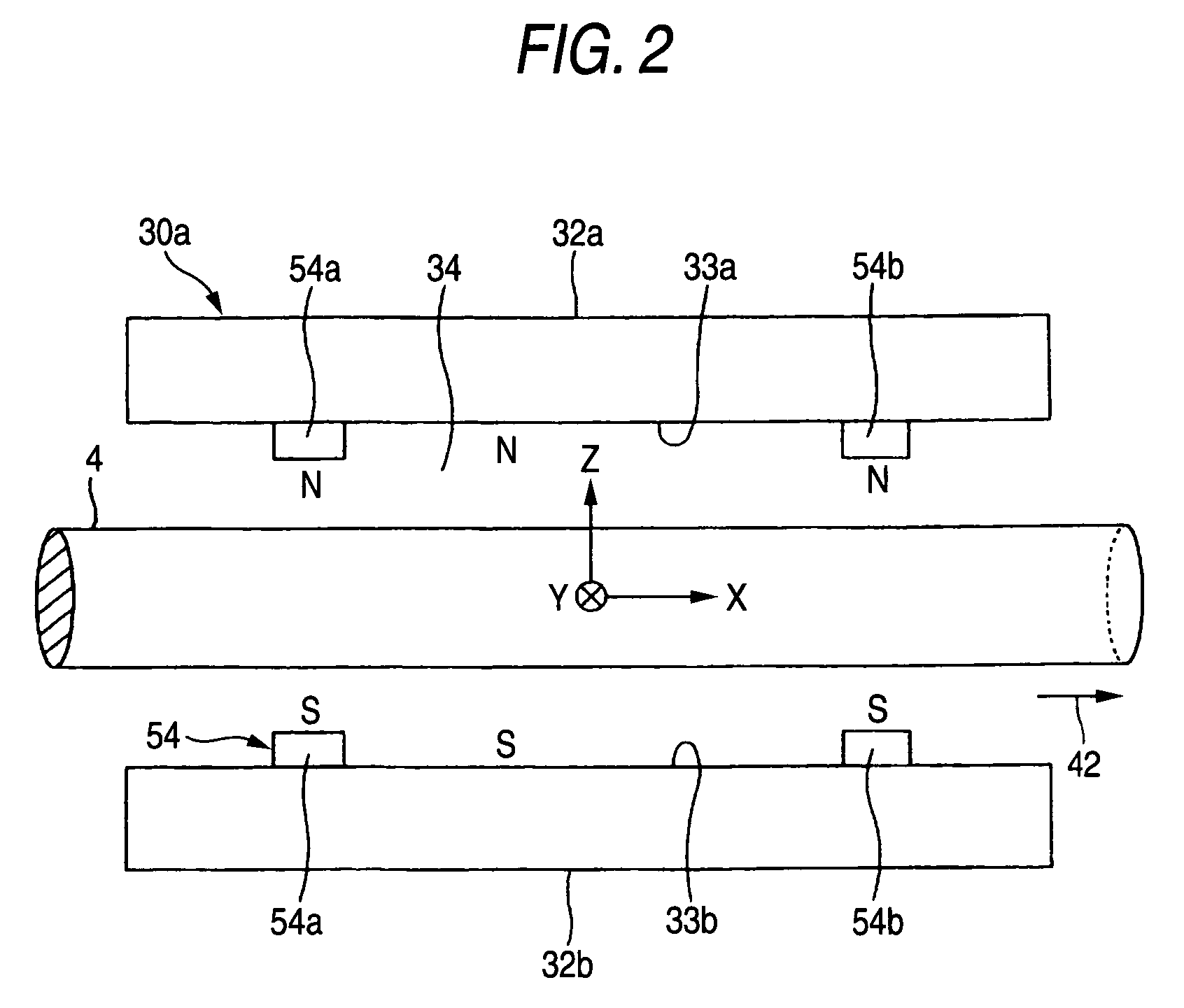
[0128]FIG. 1 is a schematic perspective view showing the deflecting electromagnet of the invention, and FIG. 2 is a schematic side view in which the deflecting electromagnet of FIG. 51 is seen from the lateral side of an ion beam passing direction, and illustration of magnetic force lines is omitted. The components which are identical or corresponding to those of the related-art example shown in FIGS. 58 to 60 are denoted by the same reference numerals. Hereinafter, description is made with placing emphasis on differences between the embodiment and the related-art example.
[0129]The deflecting electromagnet 30a comprises a permanent-magnet group 54 for, in an inter-pole space 34 between the first magnetic pole 32a and the second magnetic pole 32b, forming a mirror magnetic field in which the intensity is relatively low in the vicinity of the middle of the inter-pole space 34 in the ion beam passing direction, and the intensities in locations which are respectively nearer to the inlet...
second embodiment
[0160]In FIG. 13, examples of the magnitude |E×B| of the E×B drift in the case where the deflecting electromagnet 30b of the second embodiment is cut along the YZ-plane are indicated by the areas of hatched parallelograms. Also an example of the magnetic force lines 66a, 66b produced by the paired permanent magnets 64a, 64b are shown in the figure. Since the permanent magnets 64a, 64b form a mirror magnetic field, also the composite magnetic field B of the magnetic field produced by the magnetic poles 32a, 32b and that produced by the paired permanent magnets 64a, 64b is formed as a mirror magnetic field.
[0161]For comparison, examples of the magnitude of the E×B drift in the YZ-plane of the deflecting electromagnet 30a of the first embodiment are shown in FIG. 12. Also an example of magnetic force lines 68 produced by the magnetic poles 32a, 32b is shown in the figure. In the case of the deflecting electromagnet 30a, the permanent-magnet group (specifically, the permanent magnets 54...
third embodiment
[0178]FIG. 21 is a schematic longitudinal section view showing the deflecting electromagnet of the invention. The components which are identical or corresponding to those of the related-art example shown in FIGS. 58 to 60 are denoted by the same reference numerals. Hereinafter, description is made with placing emphasis on differences between the embodiment and the related-art example.
[0179]The deflecting electromagnet 30a comprises a pair of potential adjusting electrodes 152 which are placed so as to sandwich a path of the ion beam 4 in the same directions as the first and second magnetic poles 32a, 32b, in the inter-pole space 34 formed between the magnetic poles 32a, 32b. Specifically, the pair of plate-like potential adjusting electrodes 152 are placed respectively in the vicinities of the surfaces 33a, 33b of the magnetic poles 32a, 32b, while being electrically insulated from the magnetic poles 32a, 32b.
[0180]As shown in FIG. 21, etc., coordinate axes X, Y, Z which are orthog...
PUM
 Abstract
Description
Claims
Application Information
 - R&D
- Intellectual Property
- Life Sciences
- Materials
- Tech Scout
- Unparalleled Data Quality
- Higher Quality Content
- 60% Fewer Hallucinations
Browse by: Latest US Patents, China's latest patents, Technical Efficacy Thesaurus, Application Domain, Technology Topic, Popular Technical Reports.
© 2025 PatSnap. All rights reserved.Legal|Privacy policy|Modern Slavery Act Transparency Statement|Sitemap|About US| Contact US: help@patsnap.com


