

Circuit board having a peripheral antenna apparatus with selectable antenna elements and selectable phase shifting
a peripheral antenna and antenna element technology, applied in the field of wireless communication, can solve the problems of affecting the wireless link completely, and achieve the effect of high impedan
- Summary
- Abstract
- Description
- Claims
- Application Information
AI Technical Summary
Benefits of technology
Problems solved by technology
Method used
Image

Examples
Embodiment Construction
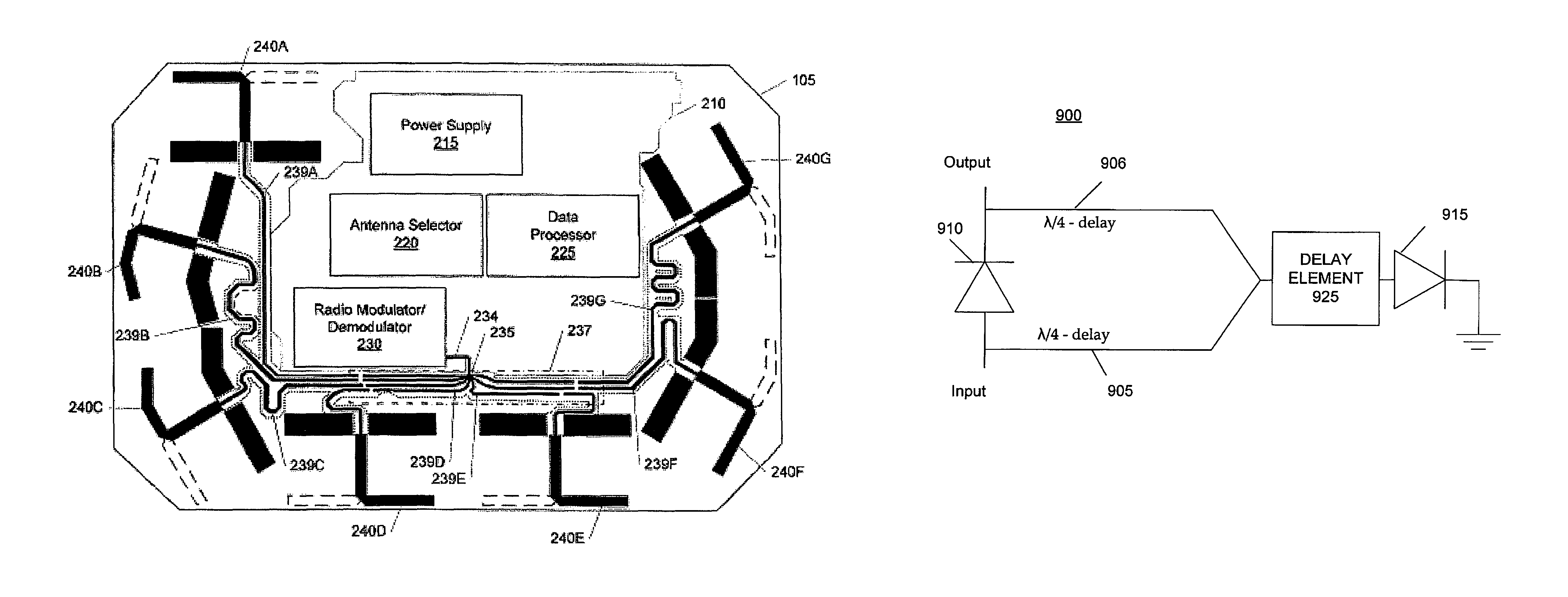
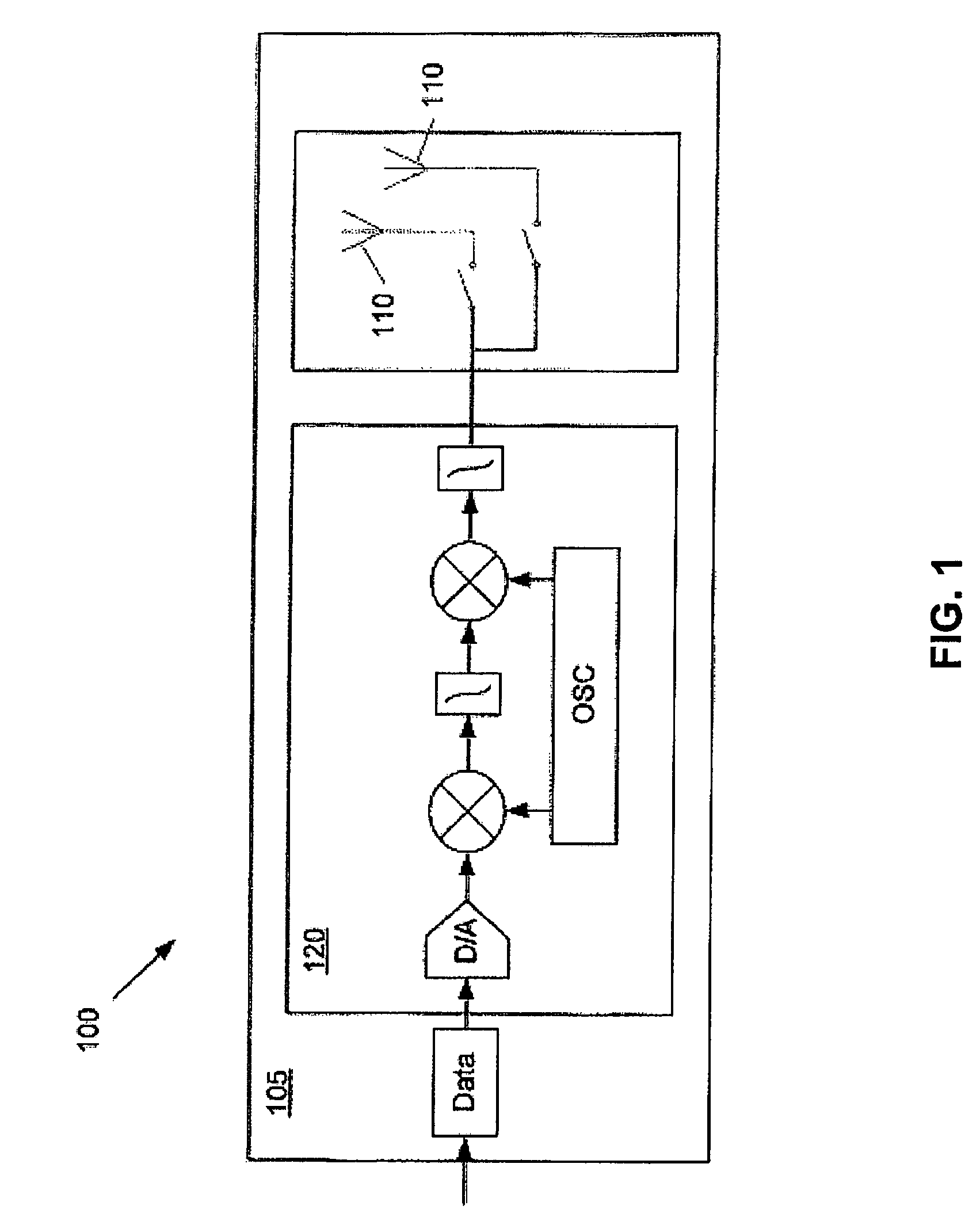
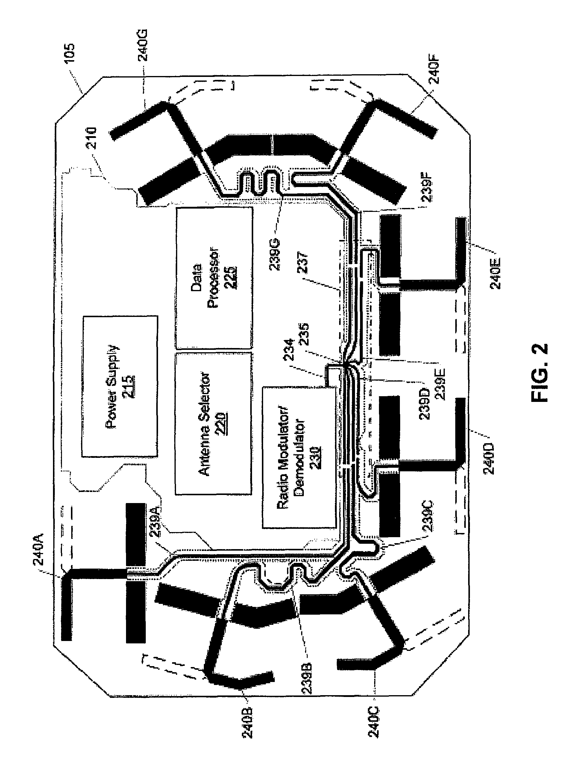
[0029]A system for a wireless (i.e., radio frequency or RF) link to a remote receiving device includes a circuit board comprising communication circuitry for generating an RF signal and an antenna apparatus for transmitting and / or receiving the RF signal. The antenna apparatus includes two or more antenna elements arranged near the periphery of the circuit board. Each of the antenna elements provides a directional radiation pattern. In some embodiments, the antenna elements may be electrically selected (e.g., switched on or off) so that the antenna apparatus may form configurable radiation patterns. If multiple antenna elements are switched on, the antenna apparatus may form an omnidirectional radiation pattern.
[0030]Advantageously, the circuit board interconnects the communication circuitry and provides the antenna apparatus in one easily manufacturable printed circuit board. Including the antenna apparatus in the printed circuit board reduces the cost to manufacture the unit and s...
PUM
 Abstract
Description
Claims
Application Information