Deterioration signal generation device for gas sensor

a technology of deterioration signal and gas sensor, which is applied in the direction of electrical control, instruments, brake systems, etc., can solve the problems of deterioration of sensor elements, troublesome switching of gas sensors in different states of deterioration, and difficulty in fabricating each of gas sensors, so as to reduce the gain of detection signals, improve versatility, and improve the effect of deterioration signal generation

Inactive Publication Date: 2009-03-03
NGK SPARK PLUG CO LTD
View PDF19 Cites 14 Cited by
  • Summary
  • Abstract
  • Description
  • Claims
  • Application Information

AI Technical Summary

Benefits of technology

[0037]The deterioration signal generation device according to the item (1) can generate a deterioration signal by outputting a reference signal acquired from a reference signal with a delay of an arbitrarily set delay time. There is no need for fabricating gas sensors as intended through accelerated life testing such that the sensors reproduce a plurality of states of deterioration in which detection signal from the gas sensors start changing with different delay times as a result of a change in a target fuel-air ratio of the mixture supplied to the internal combustion engine. There is no need for developing a system (e.g., an ECU) using such gas sensors taking the different delay times as described above into consideration. That is, a deterioration signal with a delay time which can be freely changed as described above can be obtained by simply connecting a reference sensor to the deterioration signal generation device according to the invention. Therefore, a system capable of accurate feedback control of fuel-air ratio can be developed smoothly in a short time.
[0038]Detection signals may be output with different delay times when the target fuel-air ratio is changed to the rich side and when the ratio is changed to the lean side depending on the state of contamination of the gas sensor (e.g., a state of contamination attributable primarily to Pb components included in the exhaust gas or a state of contamination primarily attributable to Si components included in the exhaust gas). Under the circumstance, the use of the deterioration signal generation device according to the item (2) makes it possible to generate a deterioration signal which is output with a delay according to a lean-rich delay time when the target fuel-air ratio is changed to the rich side and to generate a deterioration signal which is output with a delay according to a rich-lean delay time when the target fuel-air ratio is changed to the lean side.
[0040]To detect a starting point of a change in the reference signal as a result of a change in the target fuel-air ratio, as apparent from the invention set forth in the item (4), a differentiation process may be performed on the reference signal, and differentials may be compared with a threshold to identify each starting point. Thus, each starting point can be detected accurately by a simple approach.
[0041]According to the invention set forth in the item (5), a deterioration signal can be simulated from a reference signal from a reference sensor, the deterioration signal reflecting a reduction in the gain of a detection signal output by a gas sensor. Thus, the deterioration signal generation device can be provided with improved versatility. It is also possible to generate a deterioration signal having a variable delay time with the gain of the reference signal varied. Thus, a deterioration signal can be generated according to various modes of deterioration of a gas sensor.
[0043]According to the invention set forth in the item (7), a deterioration signal reflecting a reduction in response characteristics of a signal output by a gas sensor can be simulated from a reference signal of a reference sensor. Thus, the deterioration signal generation device can be provided with improved versatility. It is also possible to generate a deterioration signal having a variable delay time with the response characteristics of the reference signal varied and to generate even a deterioration signal with the gain of the reference signal varied. Thus, a deterioration signal can be generated according to various modes of deterioration of a gas sensor.
[0046]Referring to reference signals from which deterioration signals are generated, switching takes place at a lean-rich change starting point from a reference signal output by a lean-rich signal delay output unit to a reference signal output by a rich-lean signal delay output unit. At this time, if the value of the reference signal output by the rich-lean signal delay output unit is greater than the value of the reference signal output by the lean-rich signal delay output unit, the value of a deterioration signal thus generated can temporarily increase at the rich-lean change starting point from a falling state and the signal value can thereafter fall. That is, the signal can change in a wavy manner, Under the circumstance, according to the invention set forth in the item (9), a rich-lean holding signal is substituted for a deterioration signal generated by the rich-lean signal delay output unit on and after a rich-lean change starting point. As a result, the value of the deterioration signal changes from a falling state to a constant state and then enters a falling state again, whereby the signal can be prevented from changing in a wavy manner. A lean-rich holding signal may similarly be substituted for a deterioration signal output by the lean-rich signal delay output unit on and after a lean-rich change starting point, which makes it possible to prevent the value of a resultant deterioration signal from changing in a wavy manner. Thus, there will be no risk of problems such as signal abnormalities when a deterioration signal output by the deterioration signal generation device is used for a secondary purpose.

Problems solved by technology

In such a gas sensor, the sensor element is deteriorated due to aging after use for a long time because it is exposed to exhaust gas in an exhaust gas passage.
However, it is difficult to fabricate each of gas sensors as intended through accelerated life testing such that the sensors reproduce a plurality of states of deterioration to be used for such tests.
Further, it is troublesome to switch the gas sensors in different states of deterioration each time a test is conducted.

Method used


Image

  • Deterioration signal generation device for gas sensor
  • Deterioration signal generation device for gas sensor
  • Deterioration signal generation device for gas sensor

Examples


Embodiment Construction

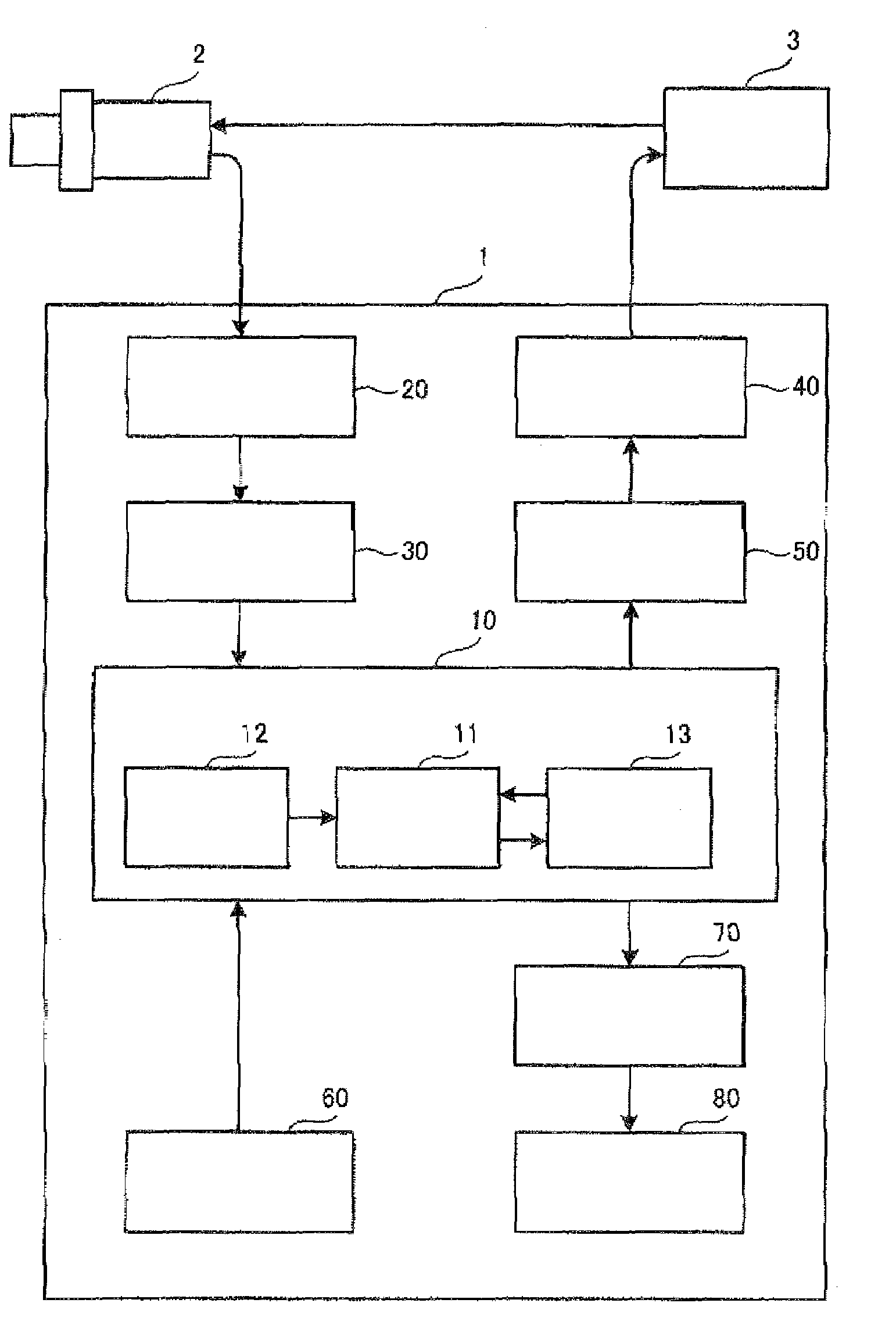
[0099]A specific embodiment of a deterioration signal generator according to the invention will now be described with reference to the drawings. FIG. 1 is a block diagram showing a schematic configuration of a sensor simulator 1 as an example of a deterioration signal generator in the present mode for carrying out the invention. An oxygen sensor, a universal fuel-air ratio sensor, or a NOx sensor may be used as a gas sensor to be connected to the deterioration signal generator according to the invention. In the present embodiment, a λ-type oxygen sensor is used as an example of such sensors, and the description will be made on an assumption that a normal λ-type oxygen sensor (which is not deteriorated) is used as a reference sensor 2. While the details of the λ-type oxygen sensor used will not be described because it is a well-known type, the description is specifically based on an assumption that a cylindrical oxygen sensor as disclosed in JP-A-2004-138599 is used.

[0100]As shown in...


PUM


Abstract

A deterioration signal generation device for a gas sensor for simulating a deterioration signal output by a gas sensor in a deteriorated state, the gas sensor detecting the fuel-air ratio of exhaust gas from an internal combustion engine based on the concentration of particular components in the exhaust gas, the deterioration signal generation device including a reference signal acquisition unit as defined herein, a reference signal storing unit as defined herein, a delay time setting unit as defined herein and a signal delay generation unit as defined herein.

Description

BACKGROUND OF THE INVENTION[0001]1. Field of the Invention[0002]The present invention relates to a deterioration signal generation device for a gas sensor which simulates a detection signal (deterioration signal) that is output by a gas sensor in a deteriorated state of the same, a gas sensor detecting the fuel-air ratio of exhaust gas from an internal combustion engine based on the concentration of particular components in the exhaust gas.[0003]2. Description of the Related Art[0004]Gas sensors are well-known. They are mounted in an exhaust gas passage of an internal combustion engine such as an automobile engine to detect the fuel-air ratio of the exhaust gas based on the concentration of particular components in the exhaust gas. A sensor element of such a gas sensor detects the fuel-air ratio of exhaust gas utilizing the fact that the magnitude of a current flowing the element itself or a voltage at the element undergoes binary or linear changes in accordance with the concentrati...

Claims


Application Information

Patent Timeline
Patent Type & Authority Patents(United States)
IPC IPC(8): B60T7/12F02D41/14G01M15/00
CPCF02D41/1495G01N27/4163
Inventor TODA, SATORUTAKAMATSU, KUNIHIKOSAWAKI, NAOTO
Owner NGK SPARK PLUG CO LTD
Why Eureka
Try Eureka