
Current sensor
a current sensor and sensor technology, applied in the field of current sensors, can solve the problems of affecting the transmission of signal current as direct current, adverse influence on the communication system, and different load applied to the application of communication systems, and achieve the effects of suppressing the whole resistance value, high sensitivity, and high precision
- Summary
- Abstract
- Description
- Claims
- Application Information
AI Technical Summary
Benefits of technology
Problems solved by technology
Method used
Image

Examples
first embodiment
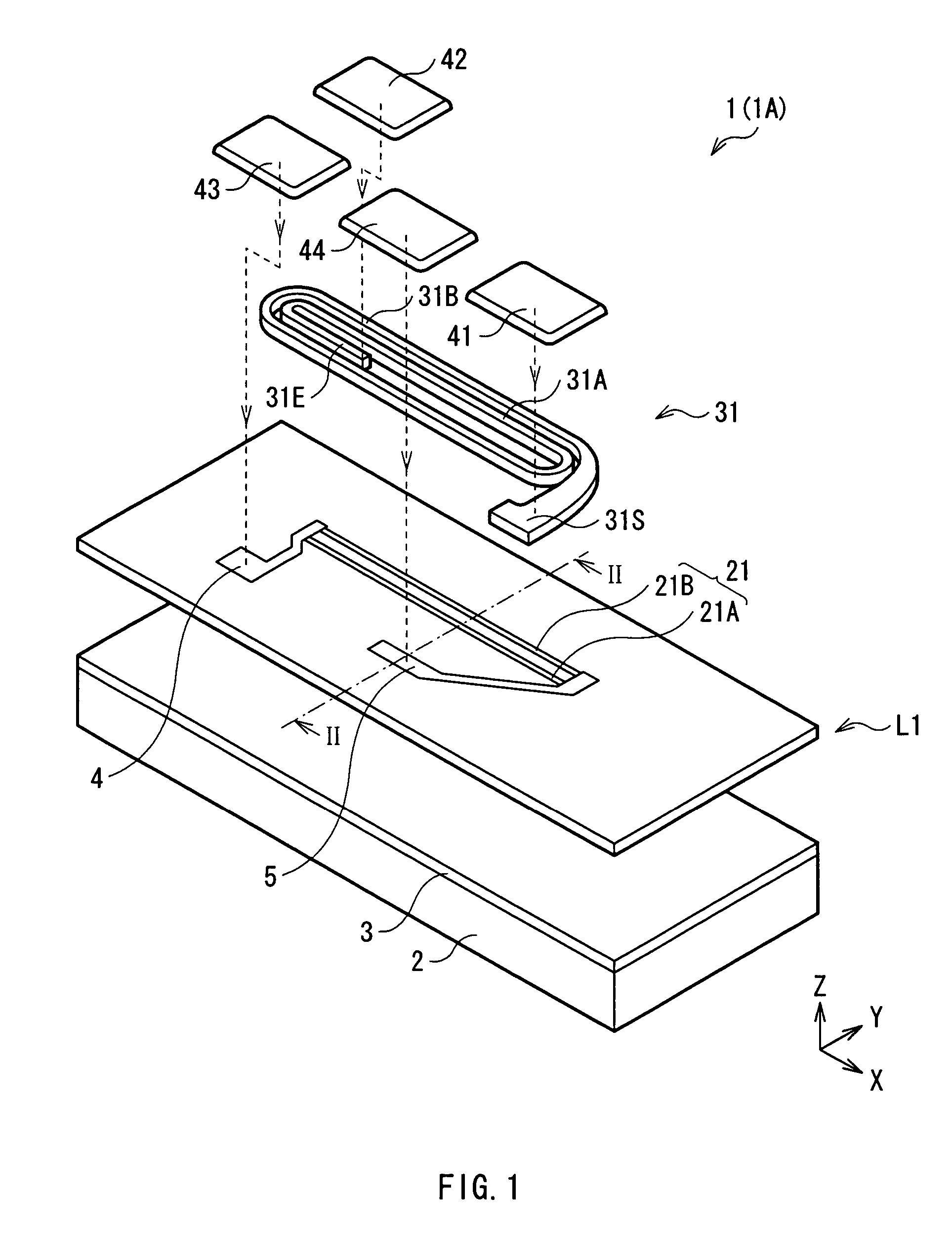
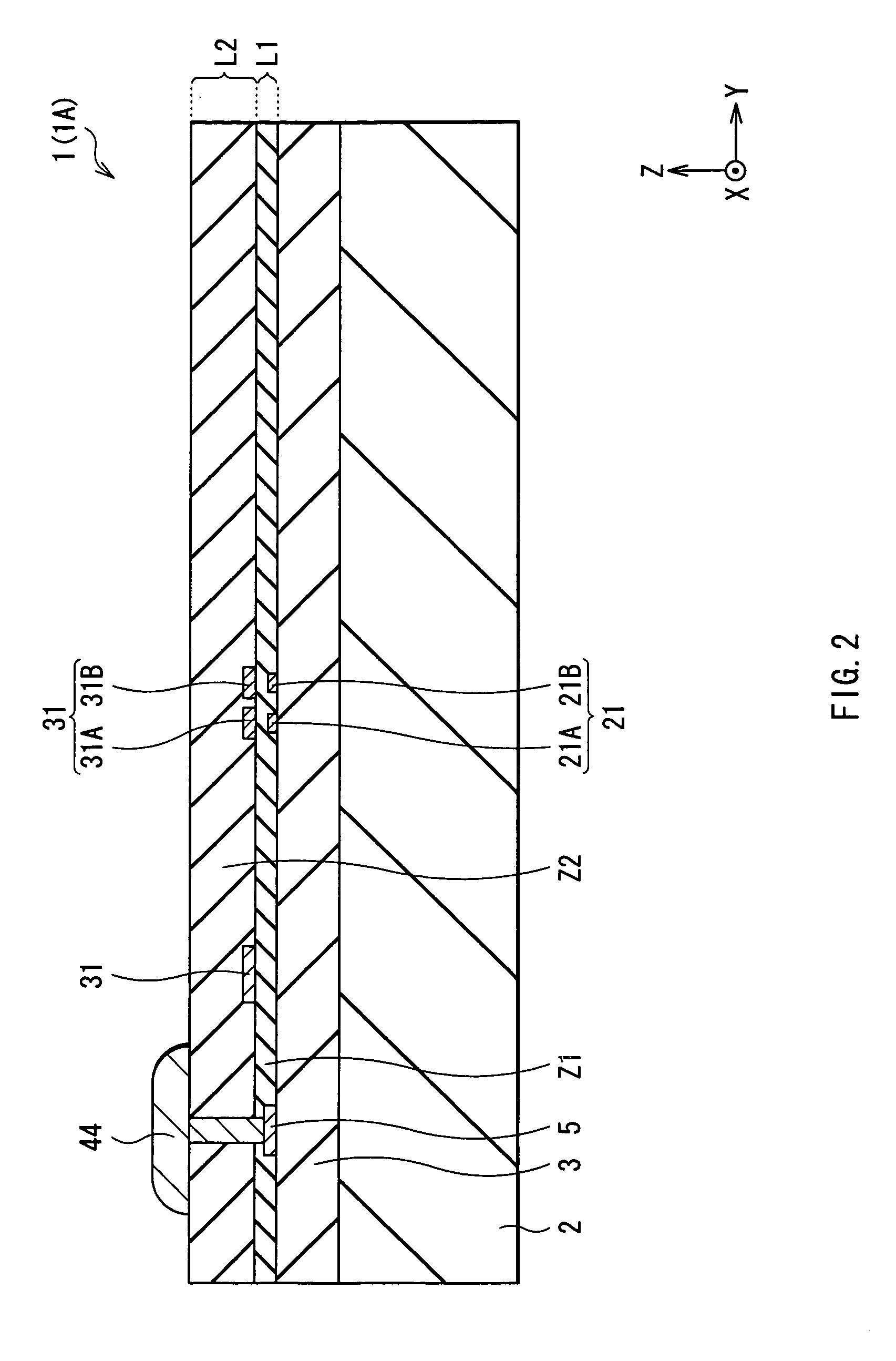
[0039]First, the configuration of a current sensor as a first embodiment of the invention will be described with reference to FIGS. 1 and 2. FIG. 1 is a schematic view illustrating a perspective configuration of a current sensor 1 according to the embodiment. FIG. 2 is a cross section taken along line II-II of the current sensor 1 illustrated in FIG. 1 seen from the direction indicated by the arrows (−X direction). The current sensor 1 is mounted on, for example, a communication device and is used for accurately measuring a current as a control signal. To distinguish the current sensor of the first embodiment from that of a second embodiment to be described later and the like, the current sensor in the first embodiment will be called a current sensor 1A.
[0040]The current sensor 1A includes a first magnetoresistive element 21 having two element patterns 21A and 21B extending in a first direction (X axis direction) at a first level L1, and a first thin film coil 31 (hereinbelow, simpl...
second embodiment
[0057]Subsequently, a current sensor 1B as a second embodiment of the invention will be described with reference to FIGS. 9 and 10.
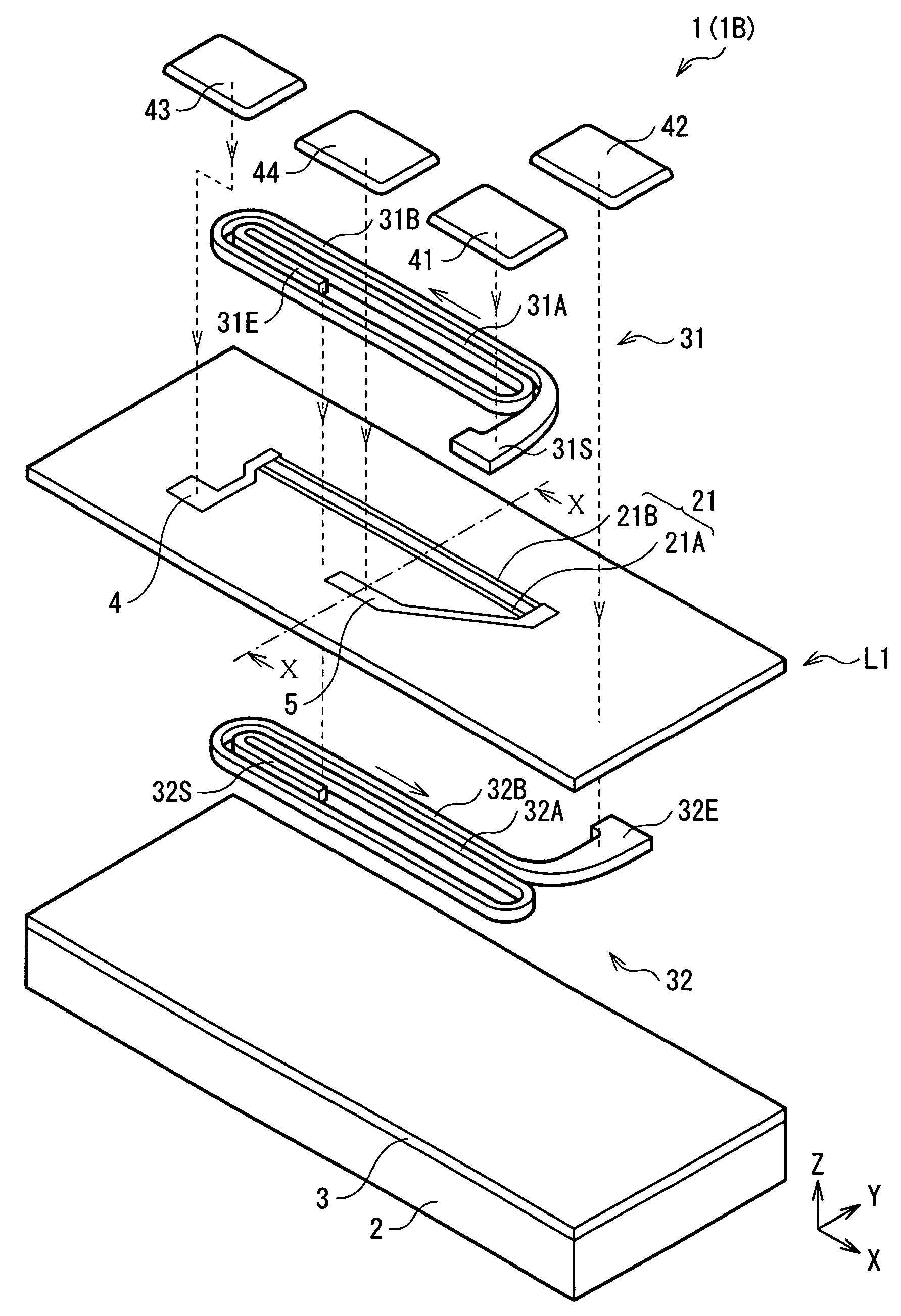
[0058]FIG. 9 is schematic view illustrating a perspective configuration of the current sensor 1B. FIG. 10 shows a sectional configuration taken along line X-X of the current sensor 1B in FIG. 9 seen from the direction indicated by the arrows (−X direction). The current sensor 1B is obtained by adding a second thin film coil 32 (hereinbelow, simply called the thin film coil 32) to the current sensor 1A of the foregoing embodiment.
[0059]Concretely, in the current sensor 1B, a third level L3 positioned on the side opposite to the second level L2 with respect to the first level L1 is provided and the thin film coil 32 is formed so as to be buried in an insulating film Z3 at the third level L3. Specifically, as shown in FIG. 10, the current sensor 1B has a structure obtained by sequentially stacking the third level L3 including the thin film coil 32, the firs...
third embodiment
[0064]Subsequently, a current sensor 1C as a third embodiment of the invention will be described with reference to FIGS. 12 to 15. FIG. 12 is a schematic view illustrating a perspective configuration of the current sensor 1C. FIG. 13 shows a sectional configuration taken along line XIII-XIII of the current sensor 1C in FIG. 12 seen from the direction indicated by the arrows (−X direction).
[0065]The current sensor 1C is obtained by adding a second magnetoresistive element 22 and a third thin film coil 33 (hereinbelow, simply called the thin film coil 33) to the configuration of the current sensor 1A of the foregoing first embodiment. It will be concretely described hereinbelow but description of parts overlapping with those of the first embodiment will not be repeated.
[0066]As shown in FIG. 12, in the current sensor 1C, the second magnetoresistive element 22 having the element patterns 22A and 22B is disposed so as to be adjacent to the first magnetoresistive element 21 in the Y axis...
PUM
 Abstract
Description
Claims
Application Information