Carbon fiber composite discharge electrode with mechanical bias

a discharge electrode and carbon fiber composite technology, applied in the direction of electrode carrying means, electrostatic separation details, solid separation, etc., can solve the problems of high cost of electrodes, and requiring strong support structures, so as to reduce the weight of electrodes and reduce the cost. , the effect of high strength

Active Publication Date: 2016-06-02
OHIO UNIV
View PDF3 Cites 0 Cited by
  • Summary
  • Abstract
  • Description
  • Claims
  • Application Information

AI Technical Summary

Benefits of technology

[0007]The invention is a new design of charging electrodes using carbon fibers to generate the corona discharge. A goal of the technology is to produce low cost electrodes that are corrosion resistant. The invention includes electrodes made of carbon fibe

Problems solved by technology

In corrosive operating conditions, the sharp spikes of the charging electrodes are also typically made of an expensive alloy (e.g., HASTELLOY brand alloy) to avoid or mitigate corrosion in the harsh environments in which such electrodes are used.
Since the entire discharge electrode

Method used


Image

  • Carbon fiber composite discharge electrode with mechanical bias
  • Carbon fiber composite discharge electrode with mechanical bias
  • Carbon fiber composite discharge electrode with mechanical bias

Examples


Embodiment Construction

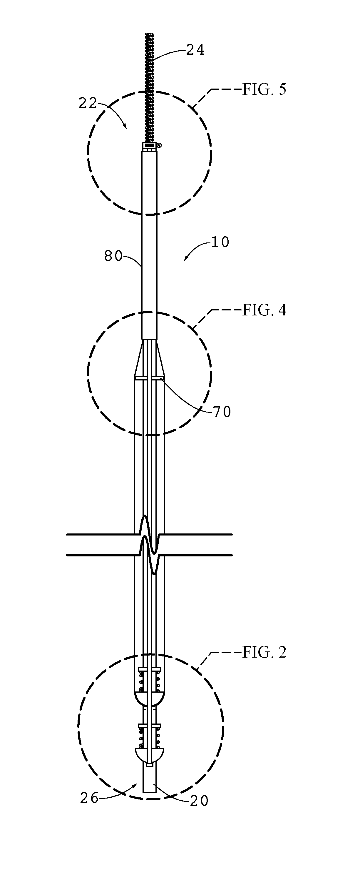
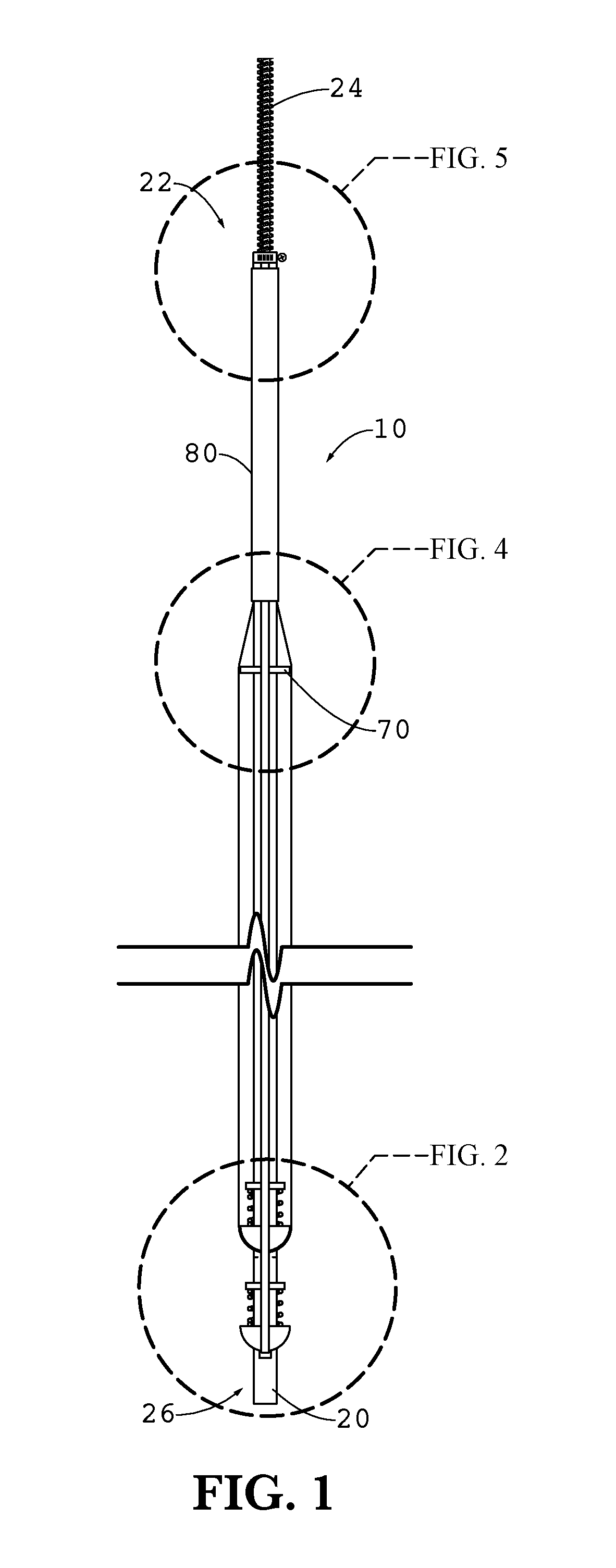
[0020]As shown in FIG. 1, a discharge electrode 10 includes a non-conductive support rod 20, such as a rod made of a polymer (e.g., poly vinyl chloride, PVC) or a glass fiber-reinforced polymer tube. Electrically conductive, non-metallic fibers such as carbon fibers and carbon nanofibers are infiltrated with a flexible polymer matrix to form at least one composite strand. In some cases in which nanofibers are in a composite, the ends of the nanofibers serve as points to support a corona. The composite strand is supported in the longitudinal direction by the support rod 20, such as by extending the conductive filaments along the rod and applying a bias in the longitudinal direction to maintain the strand in tension.

[0021]One contemplated strand is a carbon fiber reinforced polymer tape (e.g., Polyphenylene sulfide (PPS) polymer with AS4 carbon fiber) that is about 0.5 inch wide and approximately 0.007 inch thick. If different dimensions or materials are preferable, other choices are ...


PUM


Abstract

A discharge electrode using carbon fibers, nanofibers and/or nanotubes to generate the corona discharge. The invention contemplates conductive fiber, such as carbon strands with or without a polymer matrix to form a composite, and a supporting configuration in which the strand is extended along or wrapped helically around a supporting rod that extends along the length of the electrode. A mechanical bias is applied to each strand to maintain tension on the strand. Preferably this includes coil springs extending between bushings mounted on the rod and moveable hemispherical supports slidably mounted on the rod that seat against the strand.

Description

BACKGROUND OF THE INVENTION[0001]Charging electrodes are critical components used in electrostatic precipitators (ESPs), which are devices used to collect particles from gas streams, such as the streams from electric power plants burning coal. Examples of such devices are shown in U.S. Pat. No. 6,231,643 to Pasic, et al., United States Patent Application Publication No. US2008 / 0190296 published Aug. 14, 2008, and United States Patent Application Publication No. US2012 / 0227588 published Sep. 13, 2012, all of which are incorporated herein by reference.[0002]The most basic ESP contains a row of wires followed by a stack of spaced, planar metal plates. A high-voltage power supply transfers electrons from the plates to the wires, developing a negative charge of thousand of volts on the wires relative to the collection plates. In a typical ESP, the collection plates are grounded, but it is possible to reverse the polarity.[0003]The gas stream and particles flow through the spaces between ...

Claims


Application Information

Patent Timeline
IPC IPC(8): B03C3/41B03C3/60
CPCB03C3/41B03C3/60B03C2201/04B03C3/64B03C3/86
Inventor ALAM, KHAIRUL
Owner OHIO UNIV
Why Eureka
Try Eureka