Signal processor

Inactive Publication Date: 2009-03-10
PANASONIC CORP
View PDF12 Cites 9 Cited by
  • Summary
  • Abstract
  • Description
  • Claims
  • Application Information

AI Technical Summary

Benefits of technology

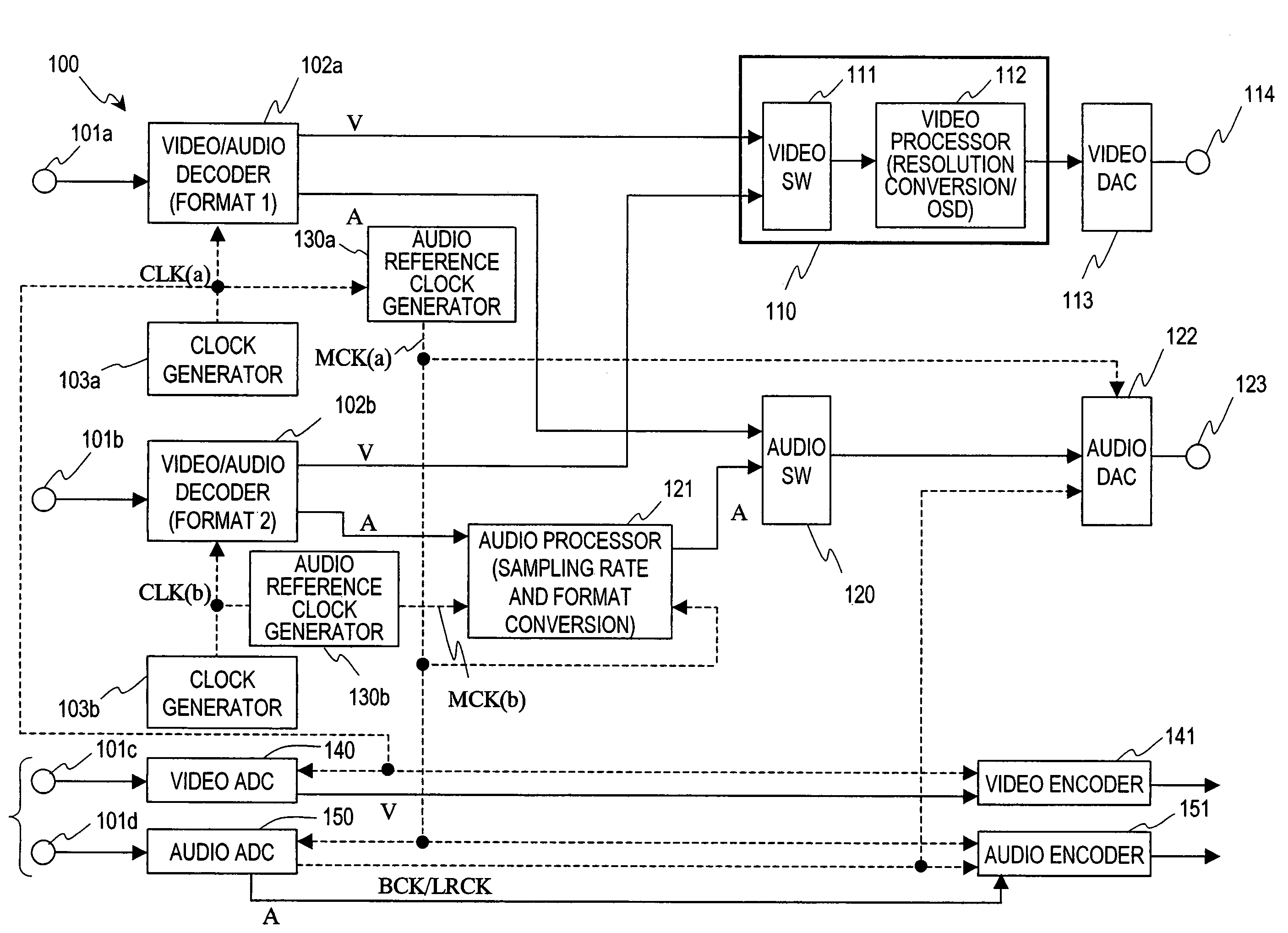
[0020]An object of the present invention is to simplify and downsize a decoder circuit, and get ready for even a complicated display demand with good video quality maintained, by providing a minimum required processing block to decode various types of signals as an independent circuit block and sharing the other processing blocks as much as possible.
[0025]A signal processor according to the present invention is provided with circuits for processing portions unique to given formats independently. However, as for the other portions, the same circuits and same reference clock signal can be shared in common, thus cutting down the cost of redundant circuits and power dissipation as well. In addition, since transmission lines do not have to be extended excessively long, those lines will not interfere with laying out other circuit components and unwanted radiation can be reduced, too. Furthermore, by providing dedicated video and audio processors for respective signal formats, various signal formats can be dealt with flexibly.

Problems solved by technology

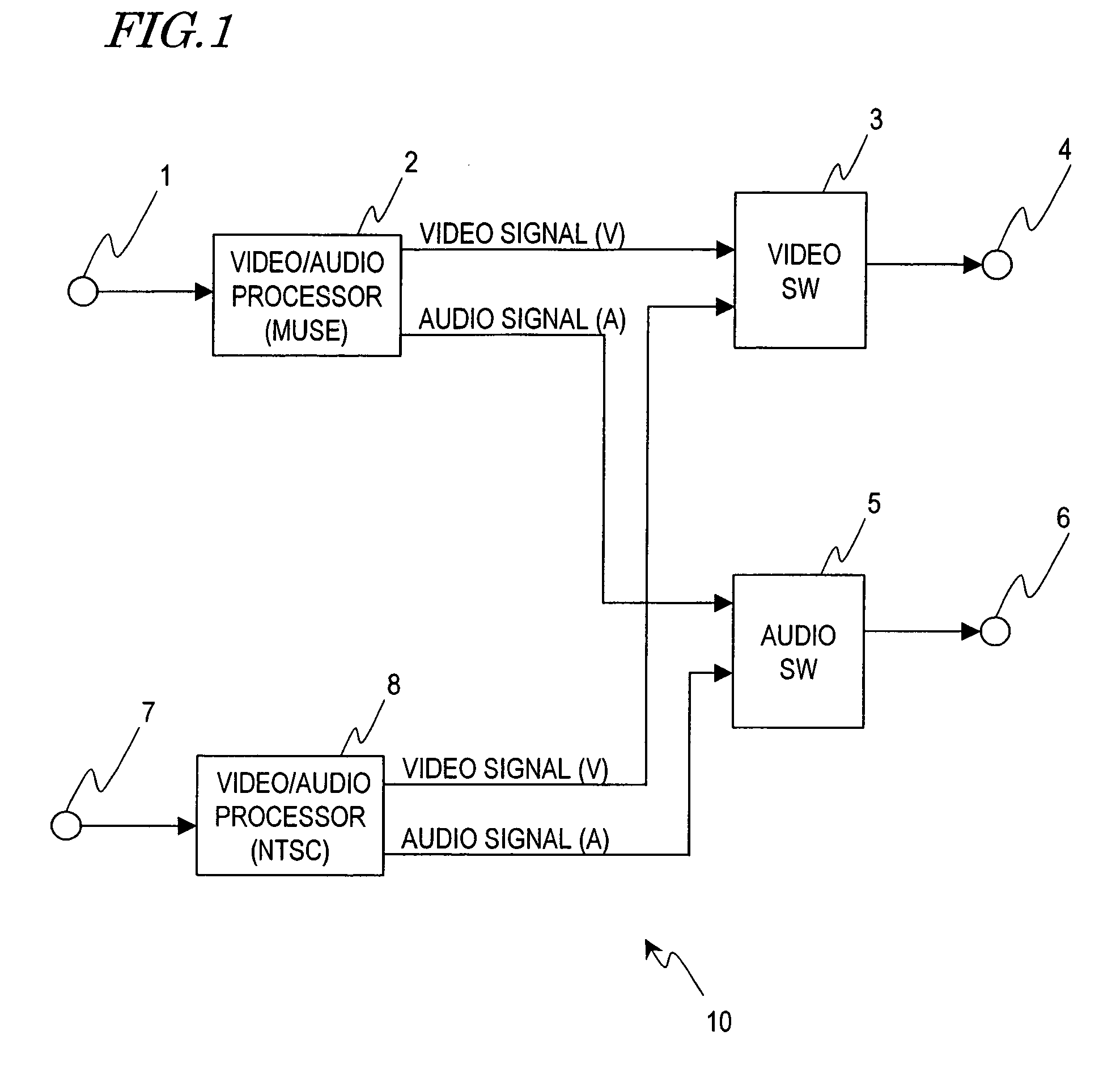
Unfortunately, though, the greater the number of types of signals to be processed, the more complicated the signal processor becomes and the more difficult it is to integrate all necessary components together on a single chip.
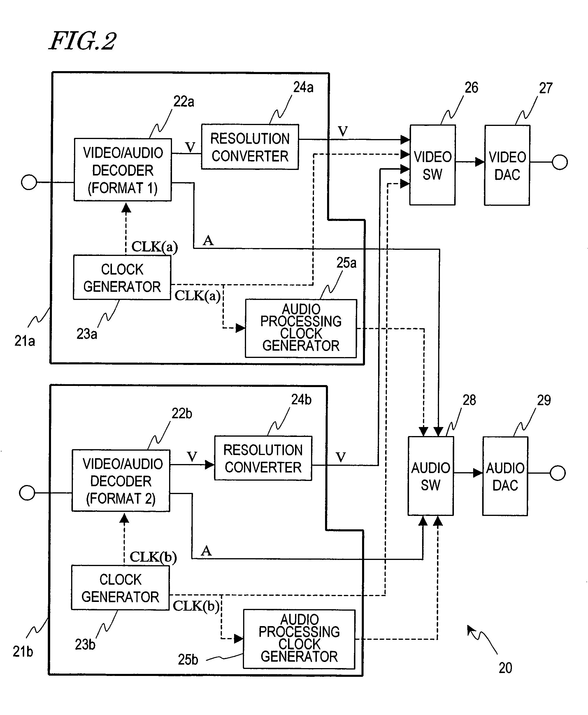
Firstly, two processing blocks need to be provided for the two different types of signals to be processed, thus requiring an increased number of redundant components. In the decoder 20, for example, two resolution converters 24a and 24b of the same type need to be provided. Then, the processing block of each signal should have an increased circuit scale. Consequently, the production cost rises and the power dissipation increases, too.
Secondly, if two different types of clock signals are needed for two different signals to be processed, then lines to transmit those clock signals must be extended a long distance to some components that are located next to their output terminals (e.g., the switches 26 and 28 in the example illustrated in FIG. 2). However, those extended lines would constitute big obstacles in laying out the other circuit components during a design process. Furthermore, such long transmission lines should increase unnecessary radiation within the circuit, too.

Method used


Image

  • Signal processor
  • Signal processor
  • Signal processor

Examples


Embodiment Construction

[0032]Hereinafter, preferred embodiments of the present invention will be described with reference to the accompanying drawings.

[0033]FIG. 3 shows an arrangement of functional blocks for an optical disc drive 30 including a signal processing chip 100 according to this preferred embodiment. The optical disc drive 30 may be loaded with a DVD 31a and a Blu-ray Disc (BD) 31b. Video data and audio data, which were encoded as an MPEG-2 program stream (PS), are written and stored on the DVD 31a. The PS consists of a plurality of data units called “packs”, each being made up of 2,048 bytes. The video and audio data are separately stored as multiple packs. On the other hand, video data and audio data, which were encoded as an MPEG-2 transport stream (TS), are written and stored on the BD 31b. The TS consists of a plurality of data units called “packets”, each being made up of 188 bytes. The video data and audio data are separately stored as multiple packets. In both of these two formats, the...


PUM


Abstract

A signal processor generates signals to reproduce video and audio from a received encoded digital signal. The signal processor includes: a first decoder for separating a first video signal and a first audio signal from a digital signal; a second decoder for separating a second video signal and a second audio signal from a digital signal; a video controller, which receives the first and second video signals, subjects a selected video signal to video processing; a clock generator for generating a clock signal of which the frequency corresponds to that of the first audio signal; an audio processor, which receives the second audio signal and the clock signal and converts the frequency of the second audio signal into that of the first audio signal; and an audio switch which outputs one of the two audio signals that is associated with the video signal being selected by the video controller.

Description

BACKGROUND OF THE INVENTION[0001]1. Field of the Invention[0002]The present invention relates to a configuration for a circuit for processing video and audio signals.[0003]2. Description of the Related Art[0004]Broadcasting technologies and video- and audio-related signal encoding technologies have recently been advanced remarkably. In the telecasting field, for example, not just conventional broadcasts at a standard resolution but also so-called “Hi-Vision” broadcasts with a higher video quality have already been brought to general home users. In the field of data compression on the other hand, MPEG-2 and MPEG-4 standards were fixed so that video and audio data can be freely read from, or written on, a storage medium such as a DVD in compliance with those standards.[0005]To make such a drive even more convenient for the users, the drive preferably has the capability of processing multiple types of signals, complying with mutually different sets of standards, by itself. Furthermore,...

Claims


Application Information

Patent Timeline
IPC IPC(8): H04N5/46H04N5/44H04N5/45H04N5/60
CPCH04N5/4401H04N5/45H04N5/46H04N5/60H04N21/4302H04N21/4316H04N21/4398H04N21/440263H04N21/4622H04N21/42646H04N21/426
Inventor UMESAKO, MINORU
Owner PANASONIC CORP
Why Eureka
Try Eureka