Method and system for using a pulsed field to assist spin transfer induced switching of magnetic memory elements

a magnetic memory element and pulse field technology, applied in the field of magnetic memory system, can solve the problems of field switching mechanism in high density memory array, significant drawbacks of programming utilizing field switching, and difficulty in detecting the magnetic storage elemen

Active Publication Date: 2009-03-10
RENESAS ELECTRONICS CORP +1
View PDF14 Cites 316 Cited by
  • Summary
  • Abstract
  • Description
  • Claims
  • Application Information

AI Technical Summary

Benefits of technology

[0014]According to the method and system disclosed herein, the present invention provides an improved mechanism for programming magnetic memories.

Problems solved by technology

Although the conventional magnetic element 10 can be programmed as depicted in FIG. 2, programming utilizing field switching has significant drawbacks.
These drawbacks may be particularly severe for higher memory densities.
For example, the field switching mechanism in a high density memory array suffers from a half selection problem.
Undesired writing may thus occur.
Furthermore field writing may not be easily scaled to higher densities due to the complicated cell structure.
Moreover, the switching current required to program the magnetic element is relatively small.
Although use of the spin transfer effect has significant benefits, one of ordinary skill in the art will recognize that there are also drawbacks.
Such a large current density passing through the conventional magnetic element 10, particularly when an insulating spacer layer 16 is used, may adversely affect the reliability of the magnetic storage cell 40.
For example, the large current density may damage or break down the insulating spacer layer 16.
Consequently, the strength of the field used in assisting switching is small, providing very little assistance in switching the magnetic element 10.
The fabrication of the conventional field line 50 increases the manufacturing complexity and may adversely affect the density of a memory using such lines 50.

Method used


Image

  • Method and system for using a pulsed field to assist spin transfer induced switching of magnetic memory elements
  • Method and system for using a pulsed field to assist spin transfer induced switching of magnetic memory elements
  • Method and system for using a pulsed field to assist spin transfer induced switching of magnetic memory elements

Examples


Embodiment Construction

[0029]The present invention relates to a magnetic memory. The following description is presented to enable one of ordinary skill in the art to make and use the invention and is provided in the context of a patent application and its requirements. Various modifications to the preferred embodiments and the generic principles and features described herein will be readily apparent to those skilled in the art. Thus, the present invention is not intended to be limited to the embodiments shown, but is to be accorded the widest scope consistent with the principles and features described herein.

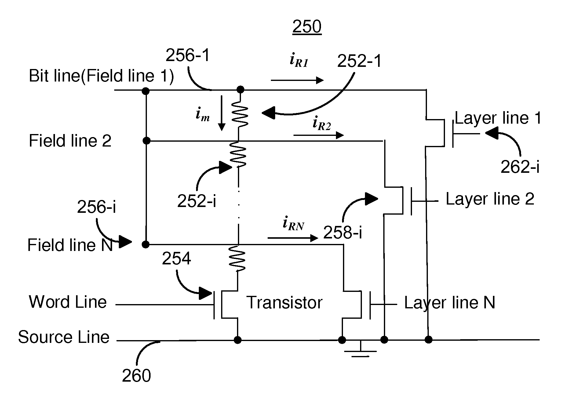
[0030]The present invention provides a method and system for providing and using a magnetic memory. The magnetic memory includes a plurality of magnetic storage cells. Each of the plurality of magnetic storage cells includes at least one magnetic element and at least one selection device. The at least one magnetic element is programmable due to spin transfer when a write current is passed through the ...


PUM


Abstract

A method and system for providing and utilizing a magnetic memory are described. The magnetic memory includes a plurality of magnetic storage cells. Each magnetic storage cell includes magnetic element(s) programmable due to spin transfer when a write current is passed through the magnetic element(s) and selection device(s). The method and system include driving a first current in proximity to but not through the magnetic element(s) of a portion of the magnetic storage cells. The first current generates a magnetic field. The method and system also include driving a second current through the magnetic element(s) of the portion of the magnetic storage cells. The first and second currents are preferably both driven through bit line(s) coupled with the magnetic element(s). The first and second currents are turned on at a start time. The second current and the magnetic field are sufficient to program the magnetic element(s).

Description

CROSS-REFERENCE TO RELATED APPLICATIONS[0001]This application is a continuation-in-part of Co-pending U.S. patent application entitled Method and System for Using a Pulsed Field to Assist Spin Transfer Induced Switching of Magnetic Memory Elements, Ser. No. 11 / 487,723, filed Jul. 17, 2006, assigned to the assignee of the present application, and incorporated herein by reference.FIELD OF THE INVENTION[0002]The present invention relates to magnetic memory systems, and more particularly to a method and system for switching magnetic storage cells using a spin transfer effect at a lower current density.BACKGROUND OF THE INVENTION[0003]FIG. 1 depicts a typical conventional magnetic element 10. The conventional magnetic element 10 can be used in non-volatile memories, such as a magnetic random access memory (MRAM). The magnetic element 10 typically includes a reference layer 14, a spacer layer 16, and a free layer 18. The free layer 18 has a magnetization having an equilibrium position alo...

Claims


Application Information

Patent Timeline
Patent Type & Authority Patents(United States)
IPC IPC(8): G11C11/00
CPCG11C11/16G11C11/5607G11C11/1659G11C11/1675G11C11/1693Y10S977/934Y10S977/935
Inventor DING, YUNFEI
Owner RENESAS ELECTRONICS CORP
Why Eureka
Try Eureka