
Model for business workflow processes

a business workflow and process technology, applied in the field of computer processes, can solve the problems of inability to perform user monitoring of transactions, inability to invoke application specific programs, and inability to achieve significant efficiency improvements

Inactive Publication Date: 2009-03-10
MICROSOFT TECH LICENSING LLC
View PDF91 Cites 18 Cited by
  • Summary
  • Abstract
  • Description
  • Claims
  • Application Information

AI Technical Summary

Benefits of technology

The present invention provides a system and method for reducing the complexity of modeling business workflow processes by using a language that facilitates modeling business workflow applications. The invention allows for the separation of communicating concurrent transactions, reducing problems associated with deadlock. The system and methodology also provide increased control and visibility over business workflow operations as compared to conventional systems and methodologies. The invention further provides a computer-readable medium and computer-executable components for creating a model of a business process. The model can be easily translated to different languages and can be used for scheduling and analyzing business processes.

Problems solved by technology

Automating such processes can result in significant improvements in efficiency, not otherwise possible.
However, this inter-company application of workflow technology requires co-operation of the companies and proper interfacing of the individual company's existing computer systems.
Therefore, application specific programs cannot be invoked and monitoring of transactions by users cannot be performed based on any actions occurring within a transaction, until the transaction fails or commits.
Consequently, the fact that a transaction is an independent transaction is not fully considered.
Additionally, concurrent transactions within a parent transaction must synchronize by communicating with one another, thus reducing overall system throughput.
Furthermore, these types of schedule software often require modification of each schedule for different technologies.

Method used


Image

  • Model for business workflow processes
  • Model for business workflow processes
  • Model for business workflow processes

Examples


Embodiment Construction

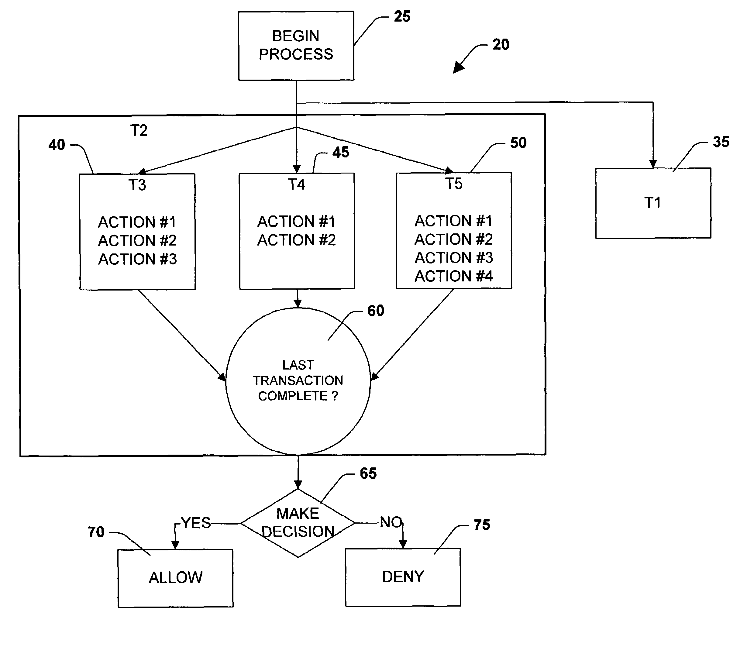
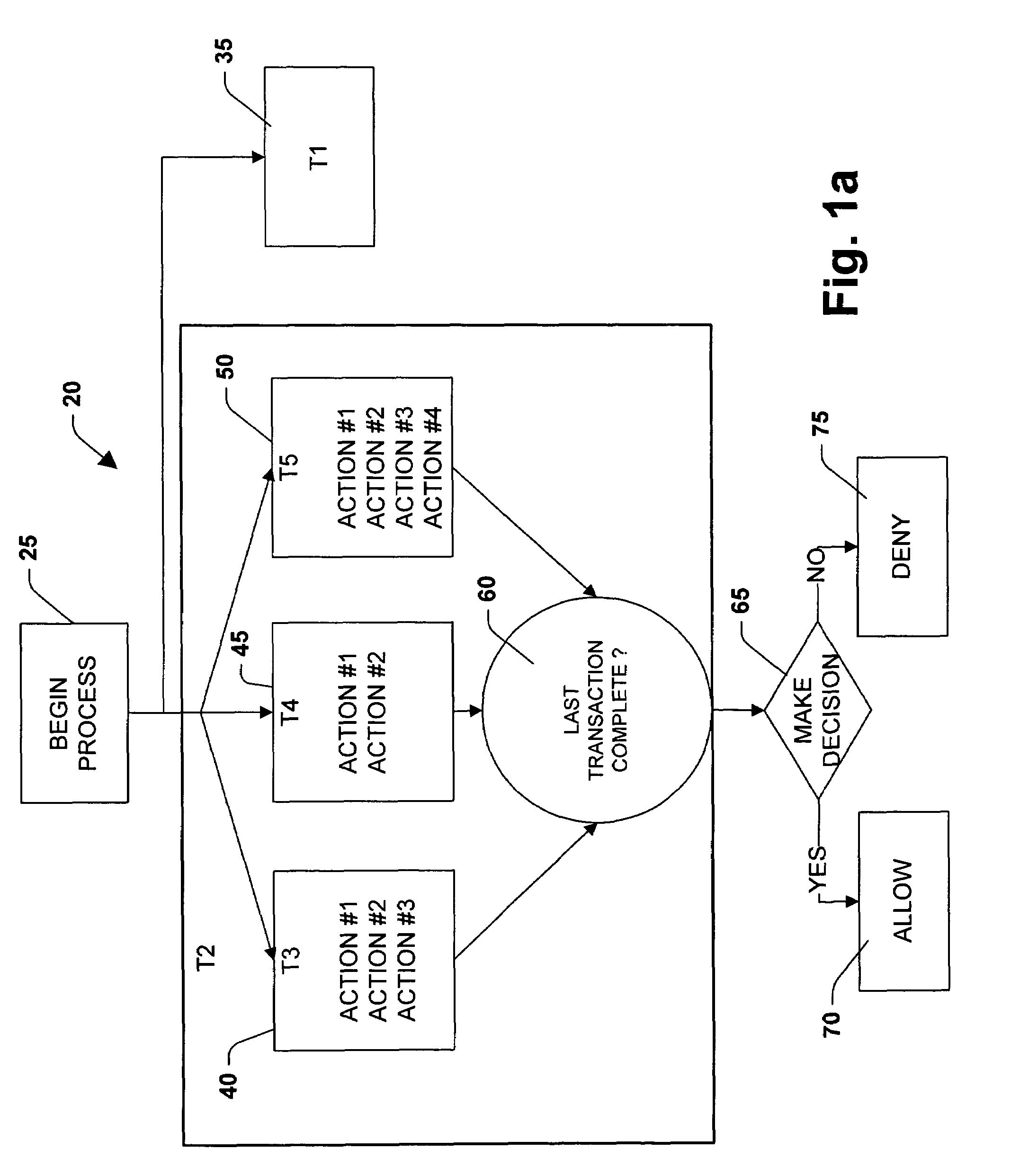
[0089]The present invention is now described with reference to the drawings, wherein like reference numerals are used to refer to like elements throughout. The present invention is described with reference to a system and method for modeling a business workflow process. The system and method employs process algebra techniques to arrive at the model. The model is reduced to an application programming language that can be utilized in a schedule file for a variety of business workflow technologies. The programming language allows users to implement various features of the model during implementation of the user's particular application to create custom business workflow models. The schedule can then be bound to application program interfaces, such as the common object model (COM) interfaces, through a separate binding file, such that the same business workflow model can be implemented for a variety of business workflow technologies.

[0090]FIG. 1a illustrates a flow diagram of a business...


PUM


Abstract

A methodology of reducing process algebra to a language that facilitates modeling a business workflow process is provided. A process algebra is reduced to a model for business workflow processes. The model is then reduced to a scheduling programming language to allow users to create models of business process by selecting between features of the model and conventional modeling features. The scheduling programming language can be represented as a graphical user interface program that is convertible to a schedule language written in a programmable language. The present invention provides for explicitly representing parallelism within the business workflow process by separating interdependent transactions from independent transactions. The isolation of certain transactions are relaxed, such that users can define transactional boundaries in order to increase granularity of the transaction at an action level and provide visibility of transactions at intermediate steps.

Description

RELATED APPLICATIONS[0001]This application is a continuation-in-part application of U.S. patent application Ser. No. 09 / 560,373 (MSFTP101US) filed Apr. 28, 2000 now U.S. Pat. No. 7,409,671 and entitled “MODEL FOR BUSINESS WORKFLOW PROCESSES” and a continuation-in-part application of a U.S. patent application Ser. No. 10 / 306,531 (MSFTP103USA) filed on Nov. 27, 2002 now U.S. Pat. No. 7,376,663 and entitled “XML-BASED REPRESENTATION OF MOBILE PROCESS CALCULI” which is a continuation of U.S. application Ser. No. 09 / 560,223, now U.S. Pat. No. 6,516,322 (MSFTP103US) filed on Apr. 28, 2000 and entitled “XML-BASED REPRESENTATION OF MOBILE PROCESS CALCULI.” This application is related to co-pending U.S. patent application Ser. No. 09 / 560,371 (MSFTP102US) filed on Apr. 28, 2000 and entitled “BINDING FOR BUSINESS WORKFLOW PROCESSES,” co-pending U.S. patent application Ser. No. 09 / 560,225 (MSFTP104US) filed on Apr. 28, 2000 and entitled “METHOD AND SYSTEM FOR HIERARCHICAL TRANSACTIONS AND COMPE...

Claims


Application Information

Patent Timeline
Patent Type & Authority Patents(United States)
IPC IPC(8): G06F9/44G06F9/46G06F7/00G06F40/143G06Q10/00
CPCG06F17/2205G06F17/2247G06F17/30896G06Q10/10G06F16/986G06F40/123G06F40/143
Inventor MEREDITH, LUCIUS G.MITAL, AMITLEVY, MARCBECKMAN, BRIANANDREWS, ANTHONY
Owner MICROSOFT TECH LICENSING LLC
Learn More