Active gas turbine lubrication system flow control

a technology of lubrication system and gas turbine, which is applied in the field of avionics systems, can solve the problems of aircraft turbine engines, inability to rely on gravity in this manner, and insufficient or inadequate oil pressure in the system,

Inactive Publication Date: 2009-03-24
HONEYWELL INT INC
View PDF21 Cites 35 Cited by
  • Summary
  • Abstract
  • Description
  • Claims
  • Application Information

AI Technical Summary

Problems solved by technology

However, aircraft turbine engines, regardless of whether they are involved with propulsive systems or non-propulsive systems such as auxiliary power or environmental cabin systems, cannot rely on the force of gravity in this manner, since they must operate through extreme attitudes in which gravity does not always operate in the same direction with respect to the engine.
These acceleration forces may cause the lubricating oil to be positioned at any portion of the tank, so that an inlet advantageously located for a gravity fed system may be starved for lubricating oil and thus cause a lower or inadequate oil pressure in the system.
However, for non-propulsive turbine machines, these methods have been found to be overly complex and thus inappropriate with respect to the less critical nature of non-propulsive turbine machines.
For example, if the aircraft is in takeoff mode or combat (surge) mode, high engine speeds are required which necessitate increased lubricating oil flow for cooling the propulsive turbine machine, but the non-propulsive turbine machines do not have such critical cooling and lubrication requirements and can sustain short periods of little or not lubrication without damage.
Such cooling requirements may have only a minimal effect on oil pressure for non-propulsive turbine machine, and necessitate the use of additional controls that respond to oil temperature.
Thus, the shaft speed at which such pumps operate is not adjustable independently of engine speed and may not be responsive to the actual lubrication needs of the engine.
This change in oil pressure may result from oil starvation at the oil pump when the aircraft changes attitude.
This arrangement reacts strictly to oil pressure and may not be able to provide sufficient oil in the event oil temperature increases, necessitating an increased flow of lubricating oil to cool turbine engine parts.
However the shaft speed of the electric motors is not responsive to the attitude of the aircraft and may not provide the amount of oil necessary for different maneuvers.
However, Pat. Appl. Pub. US2001 / 0047647 does not address the issues of using the control logic as a function of inverted flight, airframe maneuvers, or non-gravitational accelerations.

Method used


Image

  • Active gas turbine lubrication system flow control
  • Active gas turbine lubrication system flow control
  • Active gas turbine lubrication system flow control

Examples


Embodiment Construction

[0020]The following detailed description is of the best currently contemplated modes of carrying out the invention. The description is not to be taken in a limiting sense, but is made merely for the purpose of illustrating the general principles of the invention, since the scope of the invention is best defined by the appended claims.

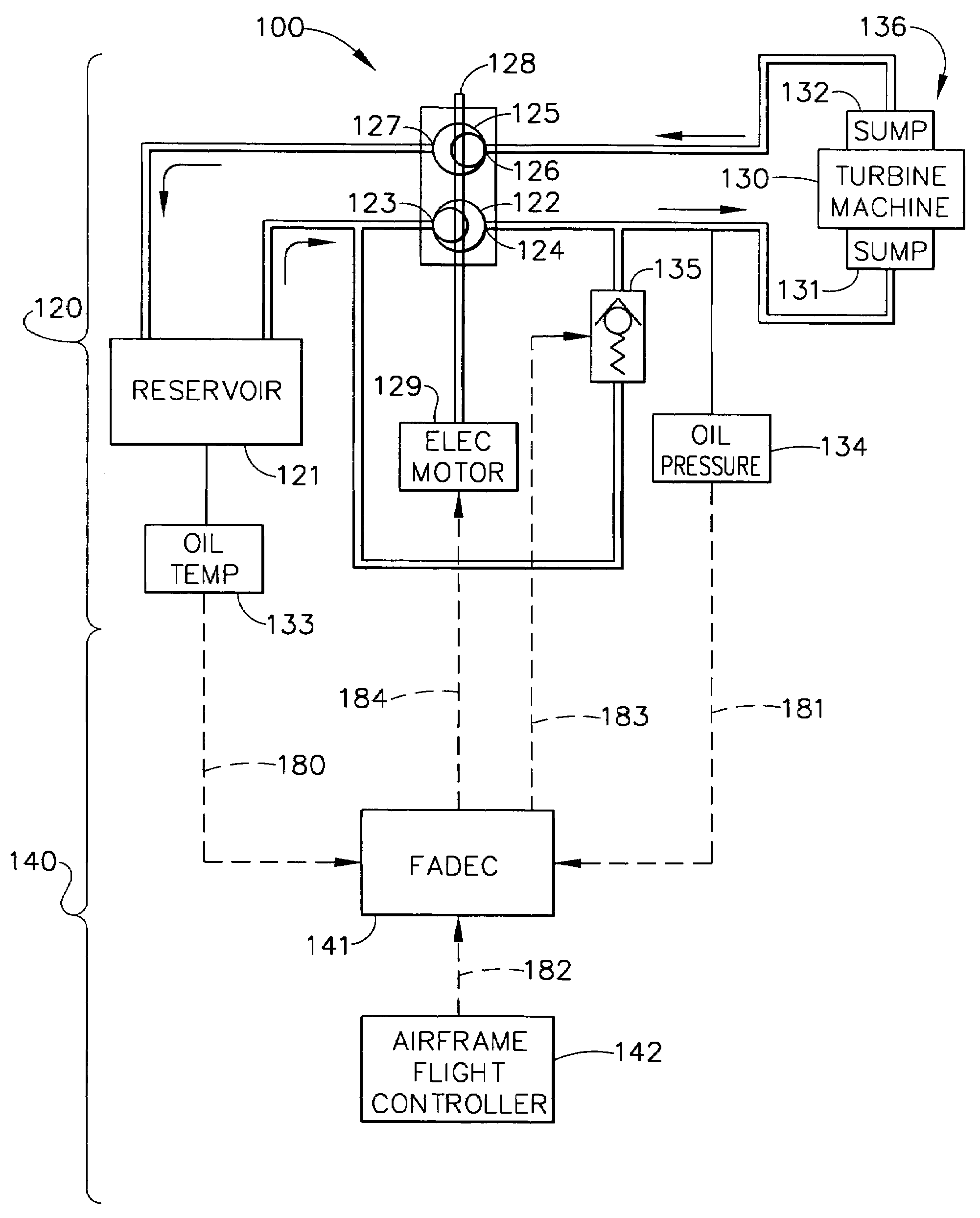
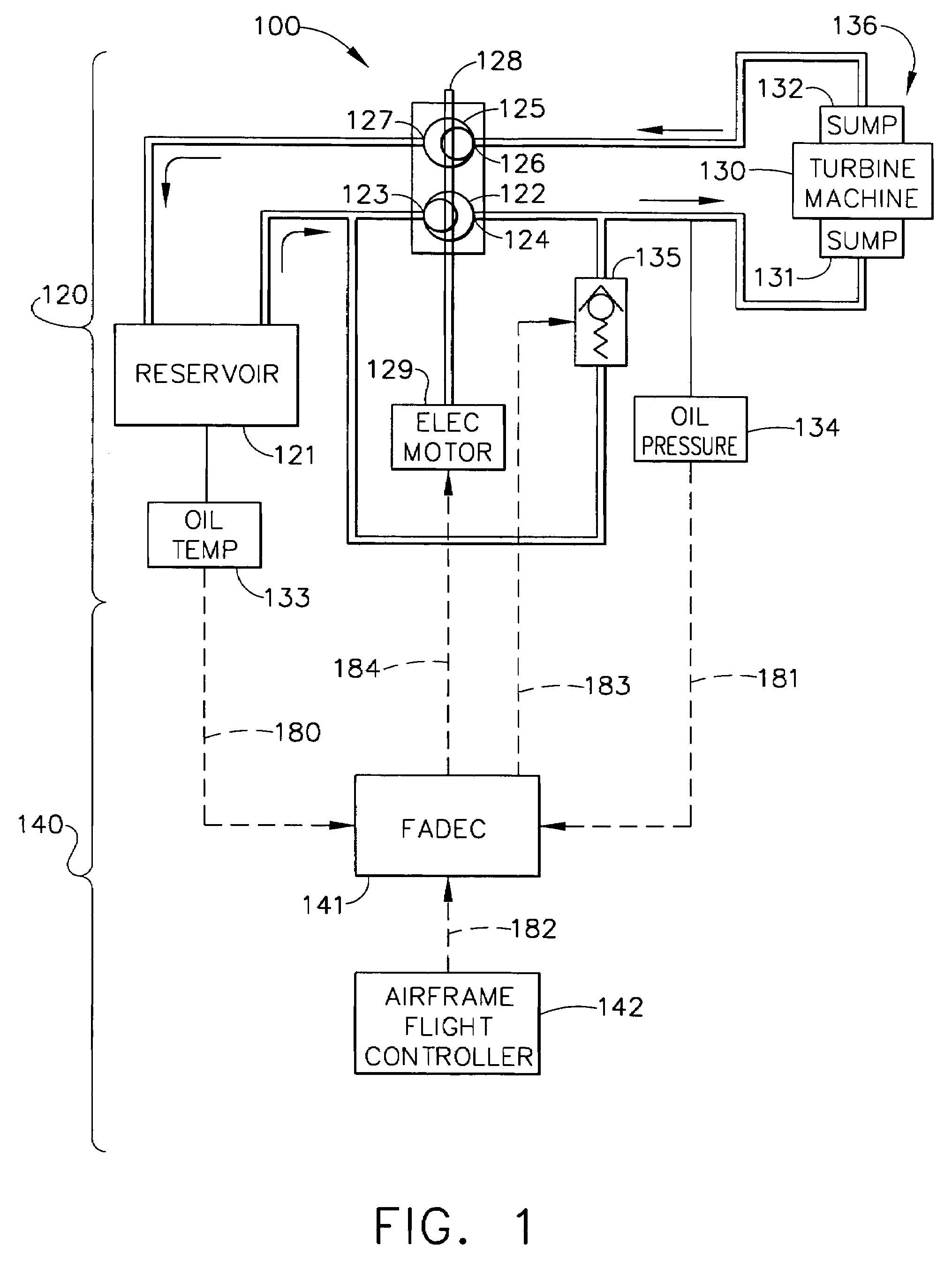
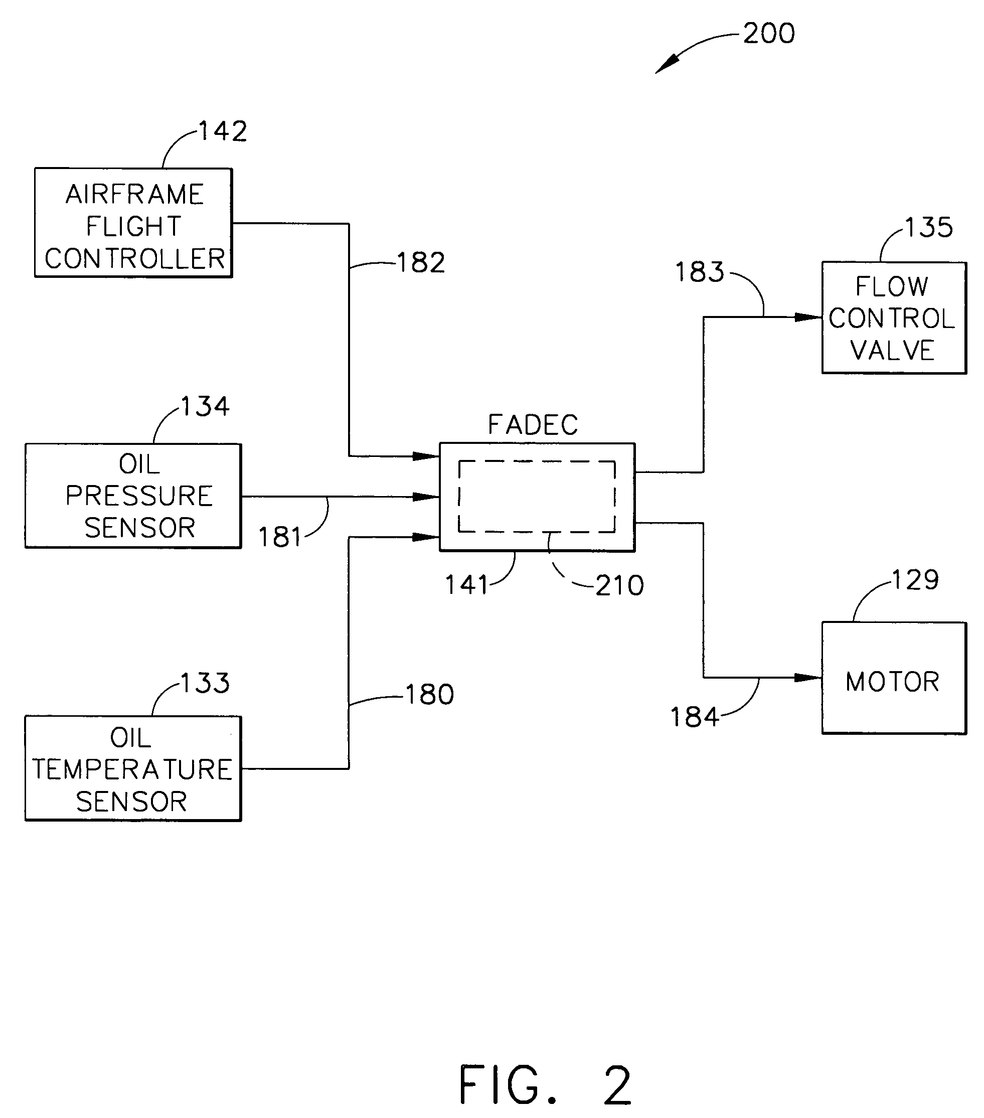
[0021]Broadly, the present invention provides a system and method for lubricating a turbine machine used on, for example, an aircraft that may undergo maneuvers that encompass normal gravitation, negative gravitation, and zero gravitation conditions. More specifically, military fighter aircraft, such as the joint strike fighter (JSF), may include non-propulsive turbine machines for purposes of auxiliary power and environmental systems operation. These aircraft may undergo often violent and extreme changes in attitude where positive, zero, and negative gravitational accelerative forces are imposed upon the aircraft systems.

[0022]The present invention pro...


PUM


Abstract

A lubrication system is provided for an aircraft turbine machine, the lubrication system being controlled by a closed-loop logic arrangement, wherein the oil pressure of a lubricant circulated therein is monitored and altered according to attitude data, acceleration data, operating mode data, or some combination thereof contained in a signal received from an airframe flight controller and according to a oil pressure signal and an oil temperature signal. The logic responsively provides a supply pump speed control signal, according to a predetermined target oil pressure value selected to correspond to the data contained in the signals. The target value may be continuously compared to the present oil pressure value and the present oil pressure adjusted by sending a motor control signal to the supply pump and a valve flow control signal to a flow control valve that conditionally allows oil from the outlet side of the supply pump to be fed back to its inlet side.

Description

BACKGROUND OF THE INVENTION[0001]The present invention generally relates to avionics systems in commercial and military aircraft, and more specifically, to the control of oil cooling and lubrication systems.[0002]Aircraft turbine engines require cooling and lubrication systems to maintain a flow of oil through the engine. Engines in general typically rely on the force of gravity to maintain the lubricating fluid, typically oil, in a reservoir providing oil for pumps moving the oil to wetted components in the machine. If the oil is in a reservoir in which the oil may collect in a known portion of the reservoir, then inlets, valving, and conduits may be reliably placed so as to the maintain the oil flow throughout the engine.[0003]However, aircraft turbine engines, regardless of whether they are involved with propulsive systems or non-propulsive systems such as auxiliary power or environmental cabin systems, cannot rely on the force of gravity in this manner, since they must operate t...

Claims


Application Information

Patent Timeline
Patent Type & Authority Patents(United States)
IPC IPC(8): F01M1/00
CPCF01D25/18F01D25/20Y10T137/0753
Inventor DELALOYE, JIM E.
Owner HONEYWELL INT INC
Why Eureka
Try Eureka