Protective coatings for molten metal devices

a technology of protective coatings and molten metals, applied in the field of components, can solve the problems of graphite components still being subject to corrosive attacks from molten metal, oxidation and corrosion of graphite components, and failure of components, so as to achieve the effect of reducing component failur

Active Publication Date: 2009-03-24
MOLTEN METAL EQUIP INNOVIATIONS LLC
View PDF350 Cites 98 Cited by
  • Summary
  • Abstract
  • Description
  • Claims
  • Application Information

AI Technical Summary

Benefits of technology

[0017]A method of applying a protective coating according to the invention comprises utilizing a frame or other structure (collectively, “frame”) to properly position the protective coating relative the non-coated component. By utilizing a frame it is more likely that the non-coated component and protective coating will be properly positioned in order to avoid the cement adhering the protective coating to the non-coated component from being of an uneven thickness, thereby helping to alleviate component failure.

Problems solved by technology

As discussed in U.S. Pat. Nos. 5,591,243 and 6,093,000, each to Cooper, the disclosures of which are incorporated herein by reference, bearing rings can cause various operational and shipping problems.
Components comprised of graphite are still subject to corrosive attacks from the molten metal.
Corrosion is usually more significant at the surface of the molten metal bath where oxygen and the molten metal interact causing oxidation and corrosion (the wearing away) of the graphite components.
Some problems with these methods of adding a sleeve to a component are (a) the cement is sometimes unevenly applied, one reason for this being that the non-coated component is sometimes not centered in the sleeve, and (b) the sliding operation can scrape away some of the cement.
Either of these factors, or others, may cause voids or air pockets in the dried cement between the non-coated component and the ceramic sleeve.
Air pockets can lead to early failure of the component including the sleeve.
Additionally, the thickness of the cement may simply be uneven, which can lead to component failure.
For example, molten metal can work its way into the air pockets and corrode the graphite behind the ceramic.
Further, the air pockets provide no structural support for the sleeve.
If something strikes the ceramic sleeve where there is an air pocket, the sleeve may break.
Also, the air in the pocket expands while the component is in the molten metal bath, which may cause the cement to separate from the component or sleeve exacerbating the aforementioned problems.
Additionally, the known methods of adding a sleeve to a component are time consuming, messy and may lead to a waste of cement.

Method used


Image

  • Protective coatings for molten metal devices
  • Protective coatings for molten metal devices
  • Protective coatings for molten metal devices

Examples


Embodiment Construction

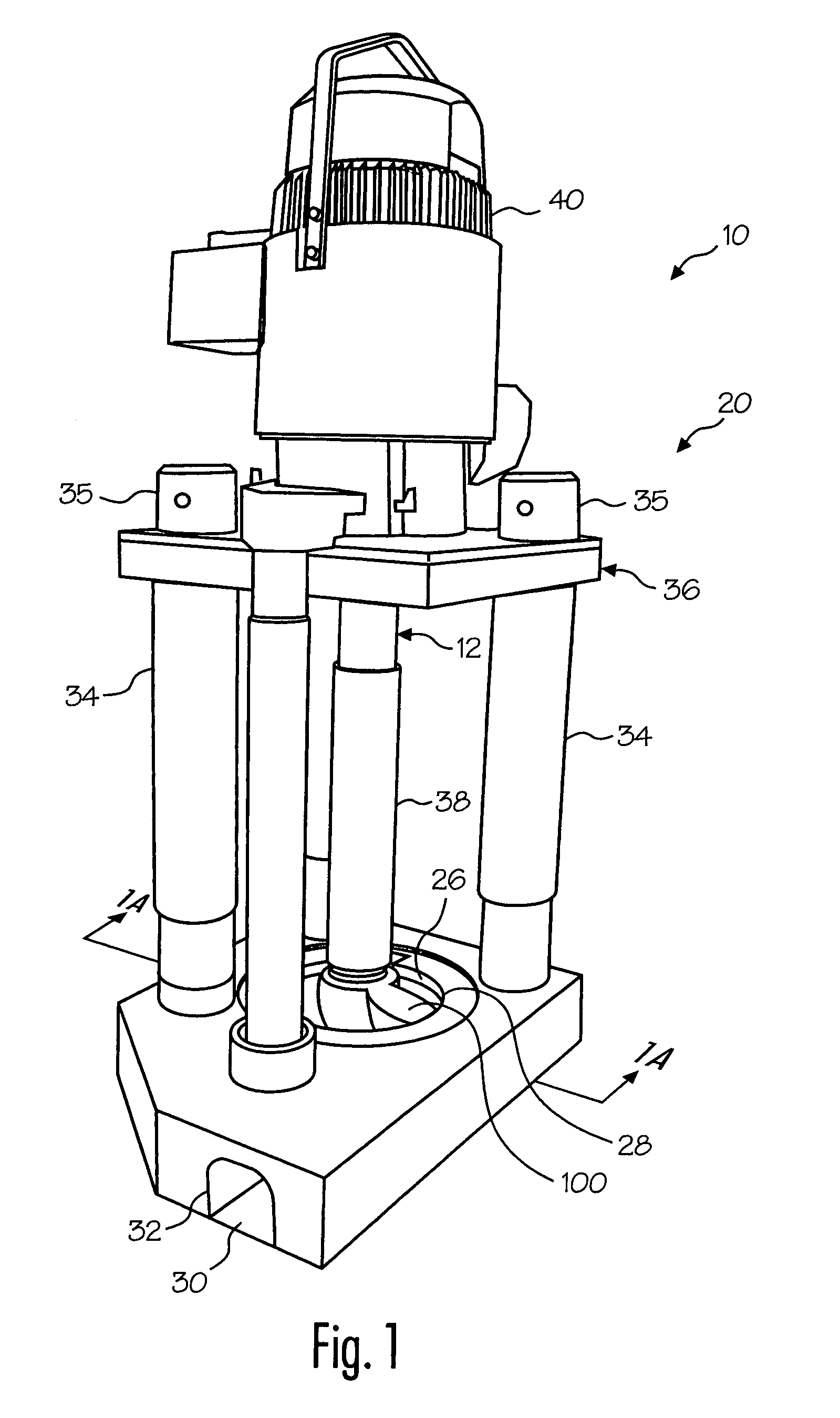
[0052]Referring now to the drawing where the purpose is to illustrate and describe different embodiments of the invention, and not to limit same, FIG. 1 shows a molten metal pump 10 in accordance with the present invention. System 10 includes a pump 20.

[0053]Pump 20 is specifically designed for operation in a molten metal furnace or in any environment in which molten metal is to be pumped or otherwise conveyed. Pump 20 can be any structure or device for pumping or otherwise conveying molten metal, such as the tangentical-discharge pump disclosed in U.S. Pat. No. No. 5,203,681 to Cooper, or an axial pump having an axial, rather than tangential, discharge, or any type of molten metal pump having any type of discharge. Basically, preferred pump 20 has a pump base 24 submersible in a molten metal bath B. Pump base 24 includes a generally nonvolute pump chamber 26, such as a cylindrical pump chamber or what has been called a “cut” volute (although pump base 24 may have any shape pump cha...


PUM

PropertyMeasurementUnit
thicknessaaaaaaaaaa
areaaaaaaaaaaa
gravityaaaaaaaaaa

Abstract

Disclosed are components covered with a protective coating for use in a molten metal bath (or comparable environment) and devices including such components. The protective coating is preferably a ceramic sleeve adhered to a non-coated component by cement. A component with the protective coating is more resistant to degradation in molten metal than is the component without the coating, and may be manufactured by the process of (a) placing the protective coating over the non-coated component, and (b) injecting cement into the space between the non-coated component and protective coating, wherein at least some of the cement is injected through a passage in either the non-coated component or the protective coating.

Description

CROSS REFERENCE TO RELATED APPLICATION[0001]This application claims the benefit of provisional application No. 60 / 395,471, entitled “Couplings and Protective Coatings for Molten Metal Devices” and filed on Jul. 12, 2002.FIELD OF THE INVENTION[0002]The invention relates to components that may be used in various devices, such as pumps, degassers and scrap melters, used in molten metal baths and to devices including such components. One aspect of the invention is a component having a protective coating, wherein the component including the coating is more resistant to degradation in a molten metal bath than is the component without the coating. The invention also relates to methods for manufacturing a component including the protective coating.BACKGROUND OF THE INVENTION[0003]As used herein, the term “molten metal” means any metal or combination of metals in liquid form, such as aluminum, copper, iron, zinc and alloys thereof. The term “gas” means any gas or combination of gases, includ...

Claims


Application Information

Patent Timeline
Patent Type & Authority Patents(United States)
IPC IPC(8): F04B17/00F04D7/06F04D13/02F04D29/02
CPCF04D7/065F04D29/026F04D13/021Y10T428/24802F05D2230/90F05D2300/611F05D2300/30
Inventor COOPER, PAUL V.
Owner MOLTEN METAL EQUIP INNOVIATIONS LLC
Why Eureka
Try Eureka