Dicing die-bonding film

a die-bonding film and die-bonding technology, applied in film/foil adhesives, semiconductor/solid-state device details, animal husbandry, etc., can solve the problems of hardly uniform application of adhesive layers, time-consuming and special devices for adhesive application, and hardly balanced two features

Inactive Publication Date: 2009-03-24
NITTO DENKO CORP
View PDF75 Cites 30 Cited by
  • Summary
  • Abstract
  • Description
  • Claims
  • Application Information

AI Technical Summary

Benefits of technology

[0037]Further other objects, features and excellent aspects of the present invention will be sufficiently understood by the following description. The advantage of the present invention will be clarified by the following description with reference to the accompanying drawings.
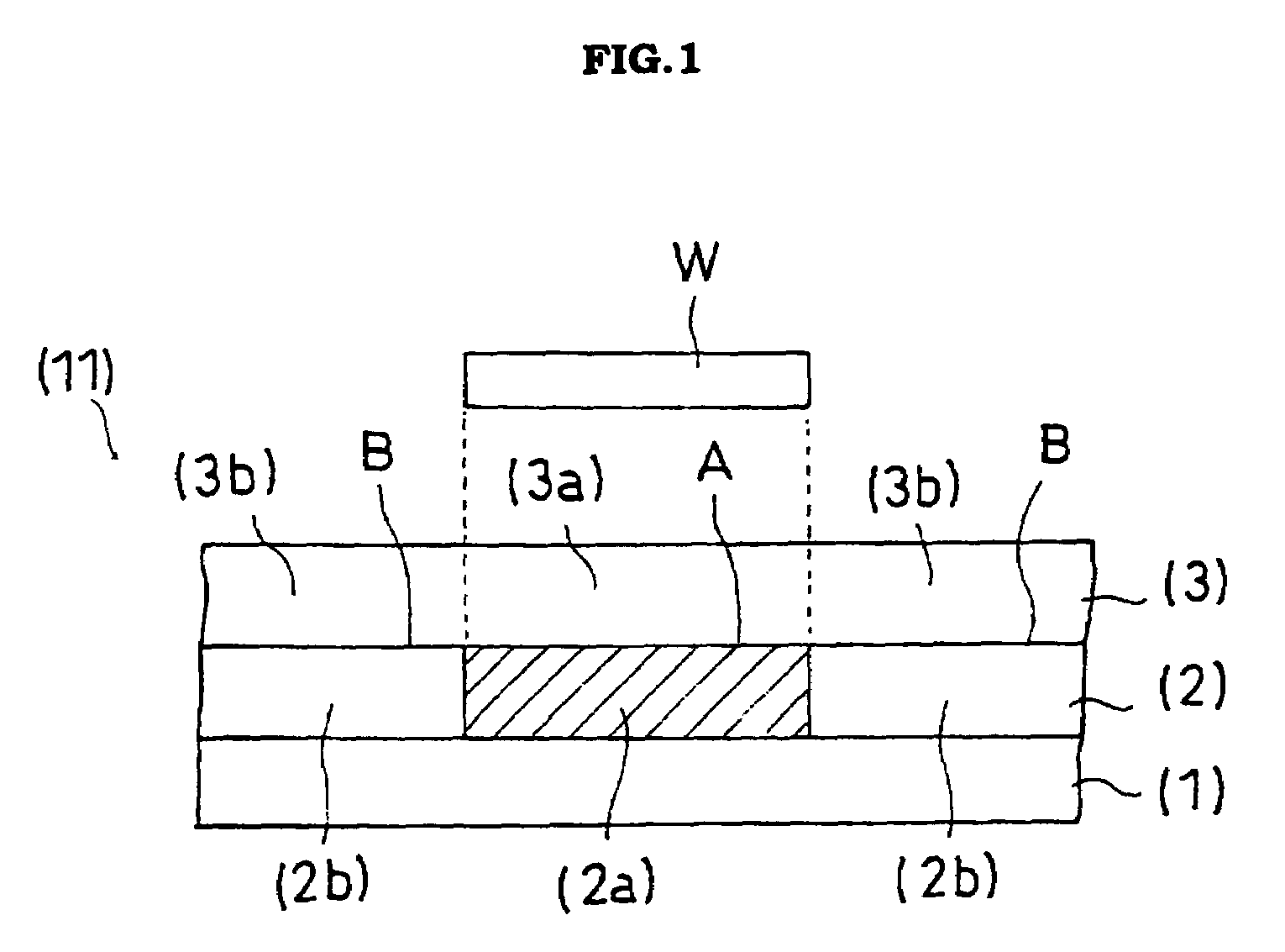
[0038]FIG. 1 is one example of a sectional view of the dicing die-bonding film (11) of the present invention.
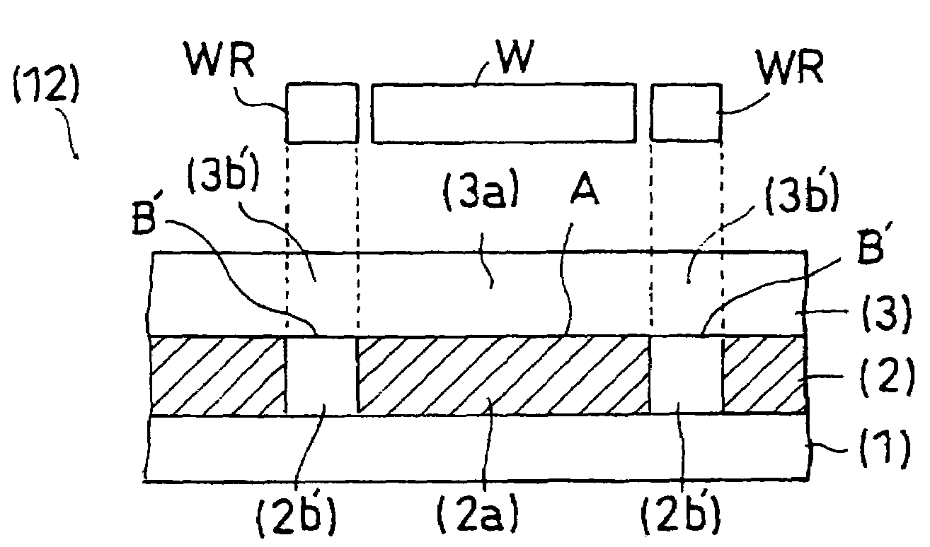
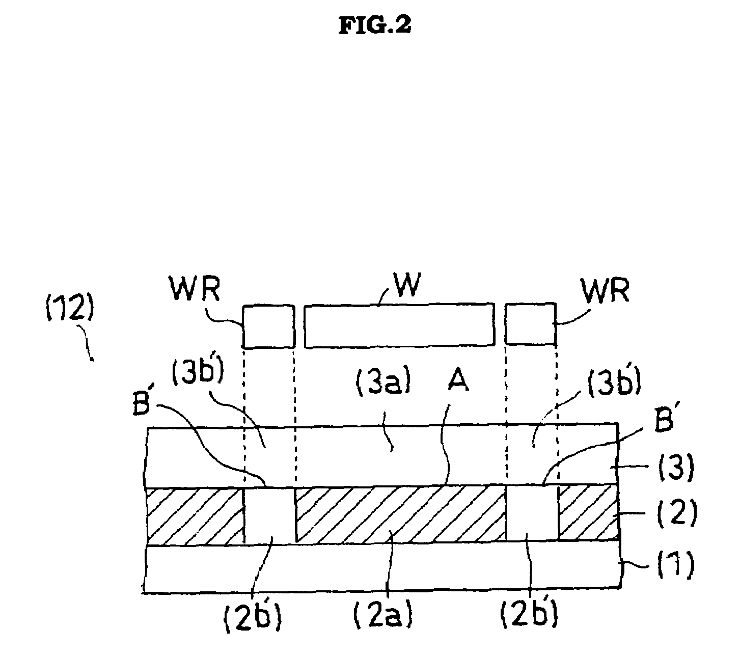
[0039]FIG. 2 is one example of a sectional view of the dicing die-bonding film (12) of the present invention.
[0040]FIG. 3 is one example of a sectional view of the dicing die-bonding film (13) of the present invention.DESCRIPTION OF THE EMBODIMENTS
[0041]Hereinafter, the dicing die-bonding film of the present invention is described by reference to the drawings. FIGS. 1 and 2 show one example of a sectional view of the dicing die-bonding film (11) of the present invention, which has a pressure-sensitive adhesive layer (2) on a substrate material (1) and a die-bonding adhesive layer (3) on the pressure-sensitive adhesive layer (2).
[0042]In FIG. 1, the respective regions (2a, 2b) are designed such that in interface (A) corresponding to the work attachment region (3a) and interface (B) corresponding to the other region (3b), the releasability of the pressure-sensitive adhesive layer (2) from the die-bonding adhesive layer (3) satisfies the following relationship: peel strength of the interface (A)>peel strength of the interface (B). The pressure-sensitive adhesive layer (2a) corresponds to the work attachment region (3a) and the pressure-sensitive adhesive layer (2b) corresponds to the other region (3b), in the die-bonding adhesive layer (3).

Problems solved by technology

In this method, however, the adhesive layer is hardly uniformly applied, and the application of the adhesive requires a special device and is time-consuming.
However, these two features are hardly balanced.
Particularly, when the adhesive layer requires high retention in a system of dicing a semiconductor wafer with a rotating round blade, it is difficult to obtain a dicing die-bonding film satisfying these features.
However, there is the case where even by this modification method, good balance between retention during dicing and releasability after dicing is hardly attained by the adhesive layer.
As a result, the peeling strength is increased to hinder pickup.

Method used


Image

  • Dicing die-bonding film
  • Dicing die-bonding film
  • Dicing die-bonding film

Examples


production example 1

(Substrate Material)

[0101]As the substrate material, linear low-density polyethylene of 70 μm in thickness was used. One side of this film was subjected to corona treatment.

(Preparation of Radiation-Curing Acrylic Pressure-Sensitive Adhesive)

[0102]70 parts of butyl acrylate (Tg in homopolymer, −55° C.), 30 parts of ethyl acetate (Tg in homopolymer, −21° C.) and 5 parts of acrylic acid (Tg in homopolymer, 106° C.) were copolymerized in a usual manner in ethyl acetate to give a solution of an acrylic polymer at a concentration of 30 wt % having a weight-average molecular weight of 800,000. The glass transition temperature of the acrylic polymer was −4.5° C. To this acrylic polymer solution were added 20 parts of dipentaerythritol monohydroxy pentaacrylate, 3 parts of a photopolymerization initiator (trade name: Irgacure 651, manufactured by Ciba Specialty Chemicals Inc.), 0.5 parts of an epoxy compound (trade name: Tetrad C, manufactured by Mitsubishi Gas Chemical Company, Inc.) and 2...

production example 2

(Substrate Material)

[0104]A polyethylene film of 80 μm in thickness was used as the substrate material.

(Preparation of Radiation-Curing Acrylic Pressure-Sensitive Adhesive)

[0105]A composition consisting of 50 parts by weight of ethyl acrylate (Tg in homopolymer, −21° C.), 50 parts of butyl acrylate (Tg in homopolymer, −55° C.) and 16 parts of 2-hydroxyethyl acrylate (Tg in homopolymer, −25° C.) were copolymerized in toluene to give a solution of an acrylic polymer at a concentration of 30 wt % having a weight-average molecular weight of 500,000. The glass transition temperature of the acrylic polymer was −37.5° C. This acrylic polymer solution was subjected to addition reaction with 20 parts of 2-methacryloyloxyethyl isocyanate to introduce a carbon-carbon double bond to a side chain of the polymer molecule. 100 parts (solids content) of this polymer was further compounded with 2 parts of a polyisocyanate-based crosslinking agent (trade name: Colonate L, manufactured by Nippon Polyu...

production example 3

(Substrate Material)

[0107]A polyethylene film of 80 μm in thickness was used as the substrate material.

(Preparation of Radiation-Curing Acrylic Pressure-Sensitive Adhesive)

[0108]A composition consisting of 95 parts of 2-ethylhexyl acrylate (Tg in homopolymer, −85° C.) and 5 parts of acrylic acid (Tg in homopolymer, 106° C.) was copolymerized in an ethyl acetate solution to give a solution of an acrylic polymer at a concentration of 30 wt % having a weight-average molecular weight of 700,000. The glass transition temperature of the acrylic polymer was −65.2° C. To this acrylic polymer solution were added 130 parts of a radiation-curing oligomer (viscosity at 25° C., 10 Pa·sec) obtained by reacting dipentaerythritol acrylate with diisocyanate, 3 parts of a photopolymerization initiator (trade name: Irgacure 651, manufactured by Ciba Specialty Chemicals Inc.) and 5 parts of a polyisocyanate compound (trade name: Colonate L, manufactured by Nippon Polyurethane Industry Co., Ltd.), where...


PUM

PropertyMeasurementUnit
adhesionaaaaaaaaaa
tensile storage elastic modulusaaaaaaaaaa
peel angleaaaaaaaaaa

Abstract

The invention relates to a dicing die-bonding film having a pressure-sensitive adhesive layer (2) on a substrate material (1) and a die-bonding adhesive layer (3) on the pressure-sensitive adhesive layer (2), wherein the adhesion of the pressure-sensitive adhesive layer (2) to the die-bonding adhesive layer (3), as determined under the conditions of a peel angle of 15° and a peel point moving rate of 2.5 mm / sec. at 23° C., is different between a region (2a) corresponding to a work attachment region (3a) and a region (2b) corresponding to a part or the whole of the other region (3b), in the die-bonding adhesive layer (3), and satisfies the following relationship: adhesion of the pressure-sensitive adhesive layer (2a)<adhesion of the pressure-sensitive adhesive layer (2b), and the adhesion of the pressure-sensitive adhesive layer (2a) to the die-bonding adhesive layer (3) is not higher than 2.3 N / 25 mm. There is thus provided the dicing die-bonding film that is excellent in balance between retention during dicing of the thin work and releasability of its diced chipped work together with the die-bonding adhesive layer, even if a work is thin.

Description

FIELD OF THE INVENTION[0001]The present invention relates to a dicing die-bonding film. The dicing die-bonding film is used in dicing a work (semiconductor wafer or the like) on which an adhesive for fixing a chipped work (semiconductor chip or the like) to an electrode member was stuck before dicing. The present invention also relates to a method of fixing a chipped work by using the dicing die-bonding film. Further, the present invention relates to a semiconductor device having a chipped work adhesive-fixed thereon by the fixing method. For example, the dicing die-bonding film of the present invention can be applied to various works such as silicon semiconductors, compound semiconductors, semiconductor packages, glass and ceramics.BACKGROUND OF THE INVENTION[0002]A semiconductor wafer having a circuit pattern formed thereon is subjected if necessary to backside polishing to regulate the thickness and then subjected to dicing into a chipped work (dicing step). In the dicing step, t...

Claims


Application Information

Patent Timeline
Patent Type & Authority Patents(United States)
IPC IPC(8): H01L29/40C09J7/20C09J133/00C09J201/00H01L21/301H01L21/58H01L21/68
CPCC09J7/02H01L24/27H01L21/6836H01L24/83C09J2201/36H01L2924/0665H01L2924/01019H01L2924/01006H01L2224/2919H01L2924/3025C09J2201/606C09J2201/61C09J2203/326C09J2205/31C09J2433/00H01L2221/68327H01L2224/274H01L2224/8385H01L2924/01005H01L2924/01013H01L2924/01015H01L2924/01016H01L2924/01027H01L2924/01029H01L2924/01033H01L2924/01047H01L2924/01051H01L2924/01061H01L2924/01074H01L2924/01079H01L2924/01082H01L2924/07802H01L2924/09701H01L2924/00H01L2924/3512C09J7/20C09J2301/208C09J2301/304C09J2301/416C09J2301/302A01K61/65Y02P60/60
Inventor MATSUMURA, TAKESHIMIZUTANI, MASAKIMISUMI, SADAHITO
Owner NITTO DENKO CORP
Why Eureka
Try Eureka