Brushless motor having a circuit board having a central hole and escape holes

a brushless motor and circuit board technology, applied in the direction of positive displacement liquid engines, pumping machines, machines/engines, etc., can solve the problems of adverse contact, inability to detect the magnetic pole position of the rotary magnet n of the hall ic qb>1/b> satisfactorily, and the height of the motor cannot be reduced, so as to achieve the effect of reducing the thickness

Inactive Publication Date: 2009-03-24
NIDEC CORP
View PDF11 Cites 25 Cited by
  • Summary
  • Abstract
  • Description
  • Claims
  • Application Information

AI Technical Summary

Benefits of technology

[0011]Hence, it is an object of the present invention to provide a brushless motor in which the electronic circuit board Q and the rotary magnet N can be disposed close to each other. It is another object of the invention to provide a brushless motor in which the magnetic pole position of the rotary magnet N of the Hall IC Q1 can be detected satisfactorily. It is another object of the invention to provide a brushless motor which can be reduced in thickness.
[0013]With this brushless motor, a distance between the rotary magnet and the Hall IC can be shortened, as a result of which the output voltage of the Hall IC increases and the detection precision of the magnetic pole position can be enhanced. Further, the motor can be reduced in thickness. Even if the motor height is the same, since the position of the stator becomes lower, a spatial margin in the motor is increased by the reduction amount between the rotor and the stator in the axial direction. Thus, since the core can be wound more, the current and speed of the motor can be reduced. That is, the freedom degree of motor design is enhanced, and it becomes possible to satisfy requirements of motor characteristics in wider range.

Problems solved by technology

Therefore, the magnetic flux density of the rotary magnet N which influences the Hall IC Q1 mounted on the electronic circuit board Q closer to the rotor becomes low, and there is a problem that the magnetic pole position of the rotary magnet N of the Hall IC Q1 cannot be detected satisfactorily.
Further, when the brushless motor is to be reduced in thickness, if the axial distances between the various parts are reduced, the winding O comes close to a surface of the electronic circuit board Q. Thus, the winding O adversely comes into contact with the electronic circuit board Q in some cases, and the height of the motor cannot be reduced.
As a result, the height of the winding is limited, and the freedom degree of the motor design is deteriorated.

Method used


Image

  • Brushless motor having a circuit board having a central hole and escape holes
  • Brushless motor having a circuit board having a central hole and escape holes
  • Brushless motor having a circuit board having a central hole and escape holes

Examples


Embodiment Construction

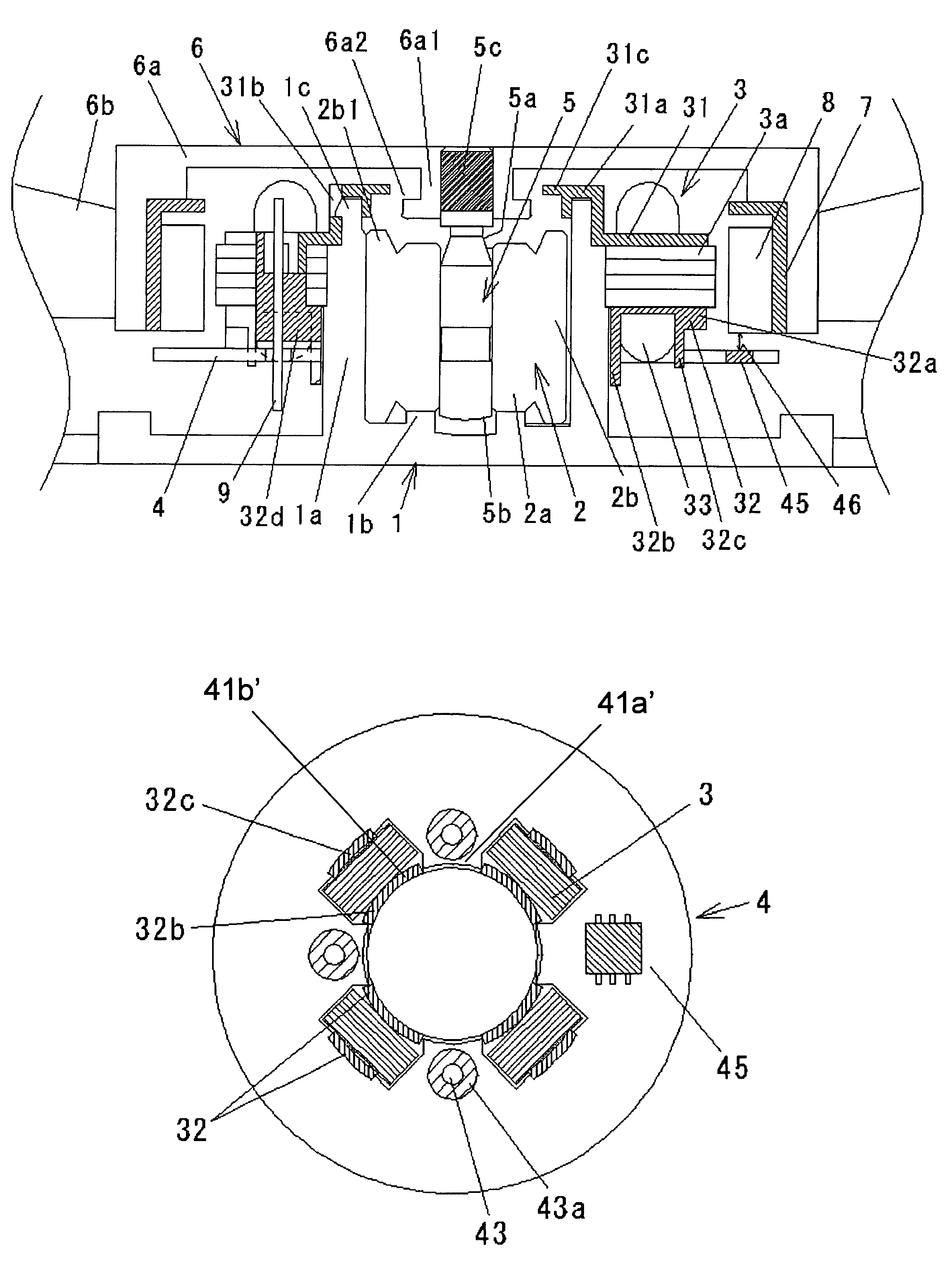
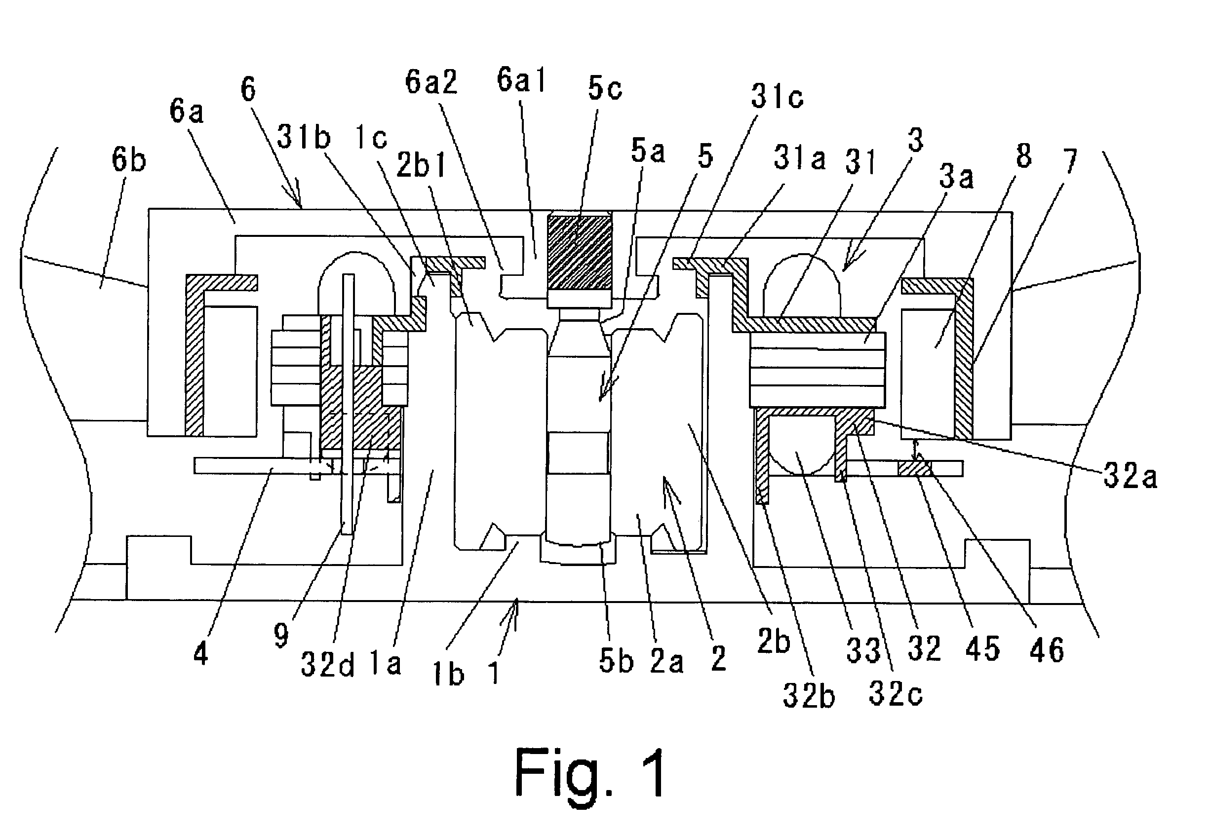
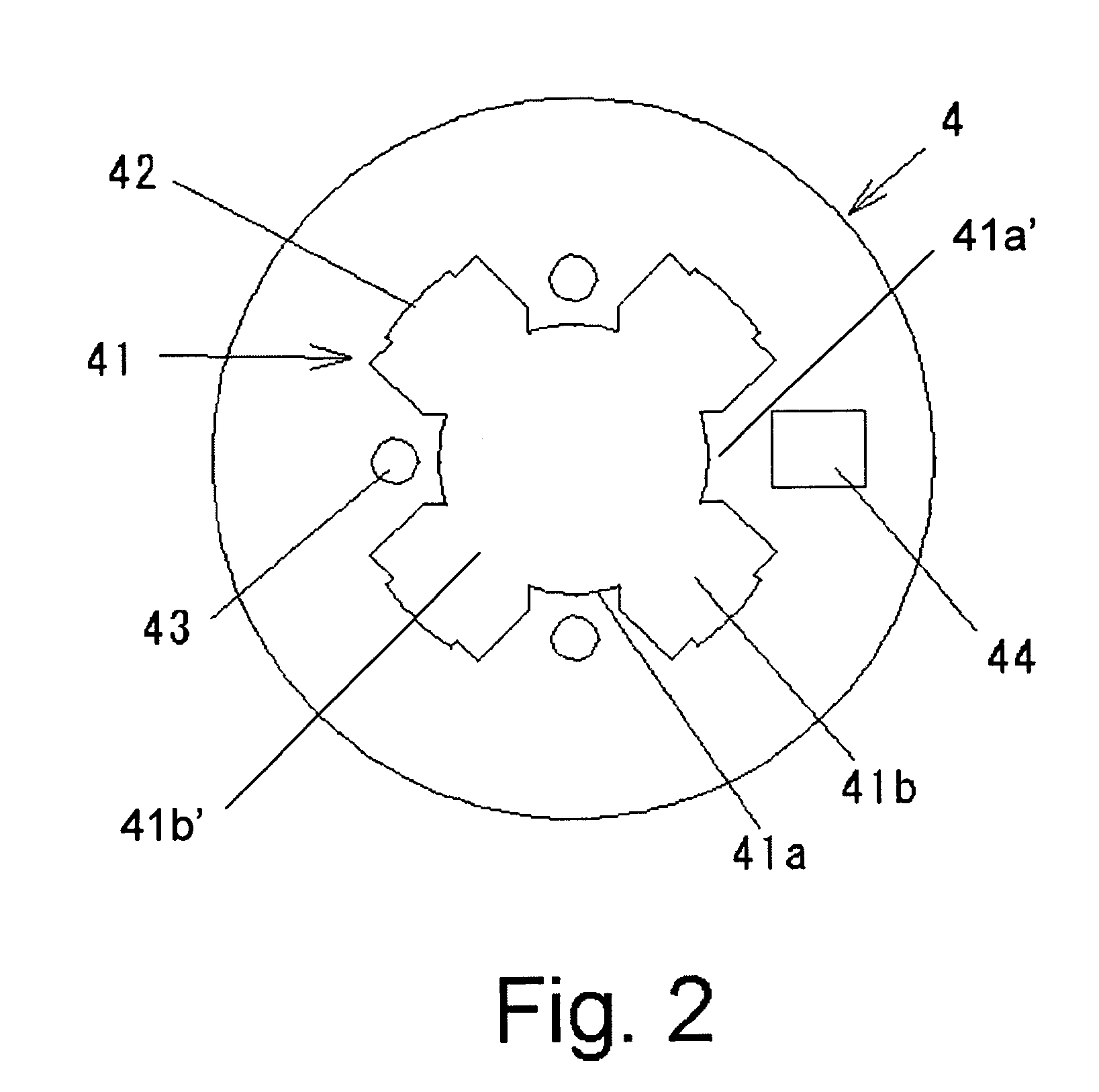
[0021]An embodiment of the present invention will be explained with reference to the drawings. FIG. 1 is an axial sectional view showing an essential portion of a brushless motor of the invention applied to a fan motor. FIG. 2 is a plan view of an electronic circuit board. FIG. 3 is an enlarged view of a stator portion, and shows positions of a winding of the stator and the electronic circuit board, and a mounting relation therebetween. FIG. 4 is a diagram of the electronic circuit board as viewed from below, and is a diagram showing a relation between a portion of the winding of the stator and an opening hole of the electronic circuit board. FIG. 5 is a diagram of a lower insulator as viewed from below.

[0022]A shallow plate-like bracket 1 is integrally formed on a central portion of an opening side of one end of a housing of a fan motor. An upper portion of the bracket 1 is opened. The housing is provided at its central portion with a bottomed cylindrical bearing holder 1a extendin...


PUM


Abstract

In a brushless motor of the present invention, by disposing an electronic circuit board and a rotary magnet close to each other, detection precision of a magnetic pole of a Hall IC is enhanced, and a motor can be reduced in thickness. The electronic circuit board 4 is provided with an opening hole 41 and a notch portion 42 provided on an outer peripheral side of the opening hole 41. A lower insulator 32 of a stator 3 is provided with a positioning surface 32a with respect to the electronic circuit board 4 and an arc projection piece 32c. Portions of coil winding portions of teeth of the stator 3 are fitted into the electronic circuit board 4, a surface of the electronic circuit board 4 is brought into positioning against an positioning surface 32a of the lower insulator 32, and the notch portion 42 of the electronic circuit board 4 and the arc projection piece 32c of the lower insulator 32 are engaged with each other.

Description

BACKGROUND OF THE INVENTION[0001]1. Field of the Invention[0002]The present invention relates to a thin brushless motor.[0003]2. Description of the Related Art[0004]FIG. 6 shows a cross section of a structure of a fan motor that is one example of a conventional brushless motor.[0005]The fan motor includes a cylindrical casing A. A bracket B is integrally formed on a central portion of one end of the casing A on its opening side through a plurality of radial arms. A cylindrical bearing holder C is fitted into a central portion of the bracket B.[0006]A pair of bearings are held on an inner peripheral portion of the bearing holder C. A shaft F which is a center of a rotation portion is fitted into the pair of bearings. The rotation portion is supported by the bearings such that the rotation portion can rotate around the shaft F. A cup-like yoke K is fixed to an upper portion of the shaft F. In impeller H is fixed to an outer peripheral surface of the yoke K. A rotary magnet N is fixed ...

Claims


Application Information

Patent Timeline
Patent Type & Authority Patents(United States)
IPC IPC(8): H02K3/50H02K11/00
CPCH02K3/522H02K29/08
Inventor SUGIYAMA, TOMOTSUGUSAIGA, AKIRAFUJIHARA, MAKOTOYABUUCHI, YUJI
Owner NIDEC CORP
Why Eureka
Try Eureka