Apparatus and method for all-solid-state fluorescence lifetime imaging

a fluorescence lifetime and imaging apparatus technology, applied in the field of time-resolved luminescence measurements, can solve the problems of reducing the cost of laser operation lifetime and subsequent operation costs, affecting the accuracy of fluorescence lifetime measurements, and not being ideal for robust and efficient measurement of nanosecond or sub-nanosecond decays. achieve the effect of more cost-effectiveness

Active Publication Date: 2009-03-24
CSEM CENT SUISSE DELECTRONIQUE & DE MICROTECHNIQUE SA RECH & DEV
View PDF11 Cites 28 Cited by
  • Summary
  • Abstract
  • Description
  • Claims
  • Application Information

AI Technical Summary

Benefits of technology

[0011]It is an object of the present invention to provide an apparatus and a method for imaging a luminescent sample that are fast and at the same time more cost-effective and more user-friendly than the systems known from the prior art.

Problems solved by technology

However, even given its intrinsic value, the spreading of FLIM instrumentation in laboratories is limited by its cost and by the required know-how necessary for its maintenance and operation.
The former can be pulsed in the pico-second range, albeit at the cost of reduced laser operation lifetime and subsequent operation costs.
LEDs can be pulsed in the nanosecond range, sufficient to obtain fluorescence lifetime information, but are not ideal for the robust and efficient measurement of nanosecond or sub-nanosecond decays.
MCPs are relatively expensive, prone to photo-damage and require elaborate electronics for operation.
Moreover, although the time properties of MCPs are optimal, their spatial resolution is relatively low, they can present “chicken-wire” artifacts caused by the fiber-optic coupling to CCD pixels, and can inject a relatively high noise level in the measurement.
The use of an MCP for wide-field detection deteriorates this performance.

Method used


Image

  • Apparatus and method for all-solid-state fluorescence lifetime imaging
  • Apparatus and method for all-solid-state fluorescence lifetime imaging
  • Apparatus and method for all-solid-state fluorescence lifetime imaging

Examples


Embodiment Construction

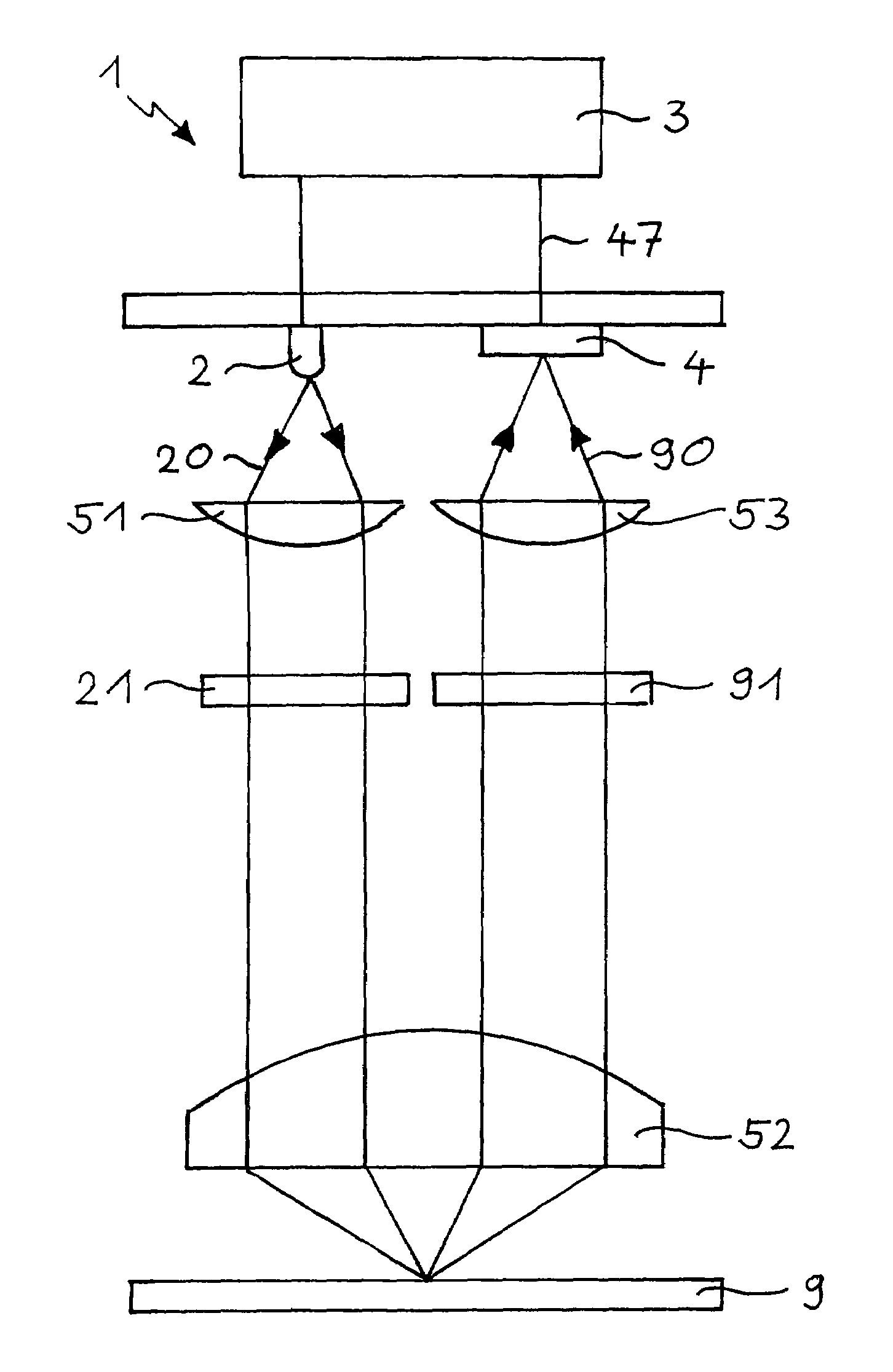
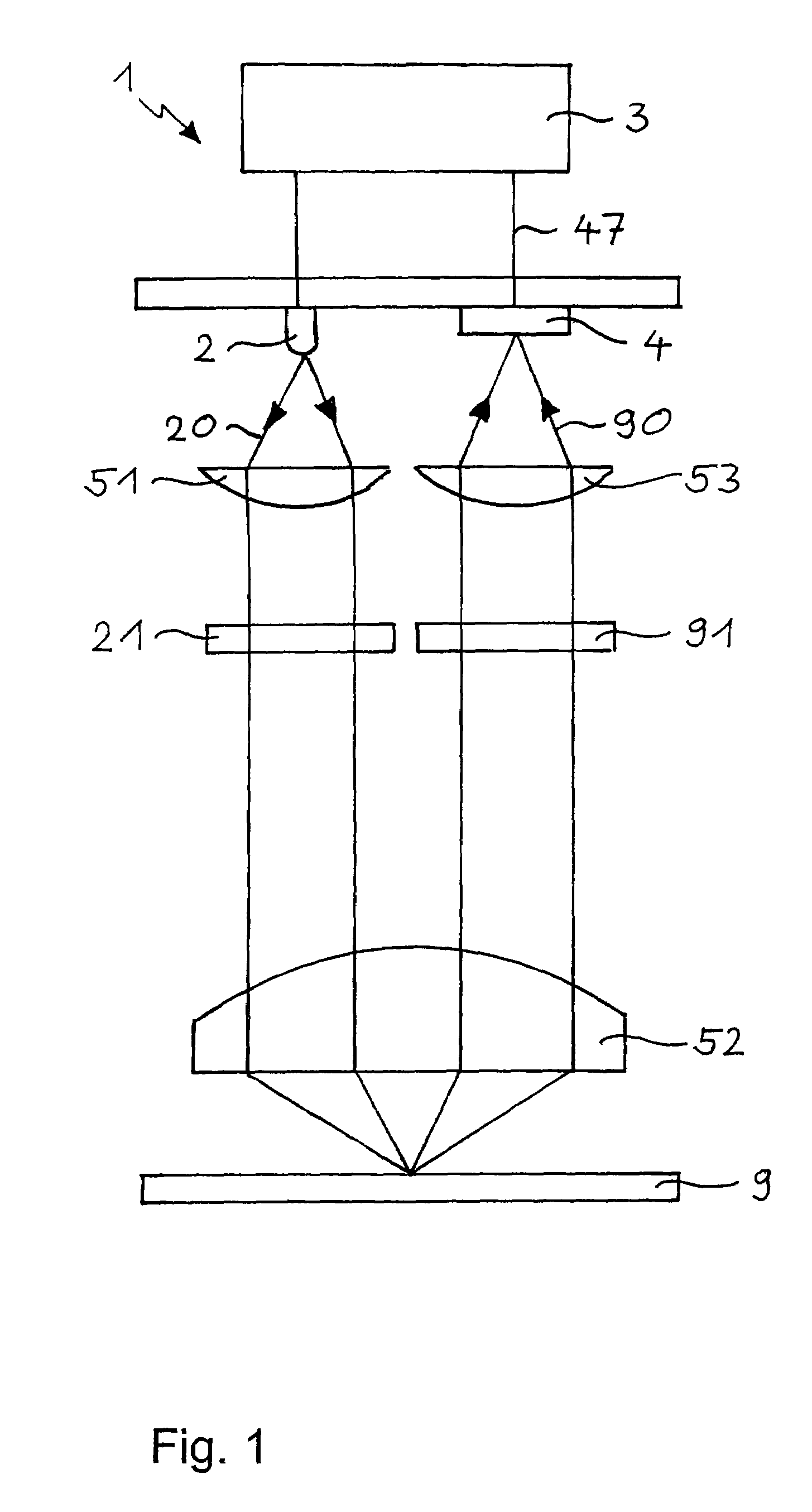
[0030]FIG. 1 schematically shows important components of the FLIM 1 according to the invention and trays of the rays therein. In an experiment, a fully automated Axiovert200M microscope (Carl Zeiss Jena GmbH, Jena, Germany) was used as the base of the FLIM 1, the necessary adaptations having been made thereto. Excitation light 20 is provided by a light source 2 modulated at a modulation frequency of, e.g., 20 MHz. The light source 2 may be, e.g., a solid-state Compass laser (Coherent Inc., Santa Clara Calif., USA) emitting light 20 at a wavelength of 405 nm, or an NSPB500S LED (Nichia Corp., Japan) peaked around 470 nm. In the latter case, the excitation light 20 is preferably filtered through an excitation filter 21. The excitation light 20, collimated by a collimating lens 51 and filtered by the excitation filter 21, is directed towards a probe 9. In an experiment, the probe 9 was turbo-sapphire (TS) green fluorescent protein. A lens 52 of the microscope is used for focusing the e...


PUM


Abstract

Fluorescence lifetime imaging microscopy (FLIM) is a powerful technique increasingly used in the life sciences during the past decades. An all-solid-state fluorescence-lifetime-imaging microscope (1) with a simple lock-in imager (4) for fluorescence lifetime detection is described. The lock-in imager (4), originally developed for 3D vision, embeds all the functionalities required for FLIM in a compact system. Its combination with a light-emitting diode (2) yields a cost-effective and user-friendly FLIM unit for wide-field microscopes. The system is suitable for nanosecond lifetime measurements and achieves video-rate imaging capabilities.

Description

[0001]This application claims priority to European application No. EP 05 015 860.9 filed Jul. 21, 2005.FIELD OF THE INVENTION[0002]This invention is in the field of time-resolved measurements of luminescence, i.e., fluorescence, phosphorescence and the like, and especially fluorescence lifetime imaging microscopy (FLIM). It relates to an apparatus and a method for imaging a luminescent sample, according to the preambles of the independent claims.BACKGROUND OF THE INVENTION[0003]The fluorescence or luminescence lifetime is the average time that a fluorochrome spends in the excited state. The sensitivity of the fluorescence (or luminescence) lifetime to environmental factors can be exploited to investigate the physico-chemical environment of fluorochromes. From the early 1990s, fluorescence lifetime imaging microscopy (FLIM) allowed the quantitative and robust imaging of pH, ion concentration, oxygen content, etc., in living cells, tissues and model organisms. Moreover, FLIM enabled p...

Claims


Application Information

Patent Timeline
Patent Type & Authority Patents(United States)
IPC IPC(8): G01J3/30
CPCG01N21/6408G01N21/6458
Inventor LUSTENBERGER, FELIXOGGIER, THIERRYESPOSITO, ALESSANDROWOUTERS, FRED SILVESTER
Owner CSEM CENT SUISSE DELECTRONIQUE & DE MICROTECHNIQUE SA RECH & DEV
Why Eureka
Try Eureka