Bent type zoom optical system, and imager, information processor and electronic camera apparatus incorporating the same

a zoom optical system and optical system technology, applied in the field ofbent-type zoom optical system, can solve the problems of still less than satisfactory in terms of size reduction, hard to achieve size reduction, etc., and achieve the effect of reducing the movement of simplifying the second lens group, and easing the load

Inactive Publication Date: 2009-03-24
OLYMPUS CORP
View PDF4 Cites 7 Cited by
  • Summary
  • Abstract
  • Description
  • Claims
  • Application Information

AI Technical Summary

Benefits of technology

[0020]Condition (1) is provided for minimizing fluctuations of an entrance pupil position. As the upper limit of 2.8 to this condition is exceeded, it causes the entrance pupil position to fluctuate largely in association with zooming, rendering it difficult to make sure optical performance. As the lower limit of 1 is not reached, it causes the effect of the second group on zooming to grow slender, rendering it hard to increase a zoom ratio.
[0023]By satisfying such conditions (1), (2) and (3), it is possible to make sure optical performance while the optical entire length is reduced.
[0030]Condition (1)′ is provided for minimizing fluctuations of the entrance pupil position. As the upper limit of 3 to this condition is exceeded, it causes the entrance pupil position to fluctuate largely in association with zooming, rendering it difficult to make sure optical performance. As the lower limit of 1 is not reached, it causes the effect of the second group on zooming to grow slender, rendering it hard to increase the zoom ratio.
[0033]If the refractive index of the prism having a reflecting surface is increased pursuant to condition (5), it is then possible to make the prism small and make the light rays through the negative single lens low, with the result that off-axis aberrations are prevented from occurring. It is also possible to have a leeway for the total-reflection angle of the prism, thereby achieving effective reflection of off-axis light rays on the wide-angle side. In addition, even with a mechanism for correction of shakes due to the movement of the prism or other element, it is possible to ensure transmission (or incidence) of off-axis light rays to (on) an imaging device.
[0044]The arrangement of this aspect is suitable for a slimmer optical system having reflecting means in the first lens group, wherein the whole optical system is made compact with a zoom ratio increased up to 7 or higher. By locating the principal points of the negative single lens L1 in the first lens group on the object side, it is possible to locate the rear principal point throughout the first lens group on the image side. It is thus possible to narrow down the principal point space between the first lens group and the second lens group at the wide-angle end, thereby easing loads on the second lens group, so that the amount of movement of the second lens group can be minimized, and the second lens group can be simplified as well. Further, by easing loads of the second lens group on zooming, it is possible to minimize the amount of movement of the second lens group, and simplify the arrangement of the second lens group as well. Because of the need of easing the loads of the second lens group on zooming, there is a lot more load applied on zooming by the lens group unit A. For this reason, the space of the lens group unit A from the wide-angle end to the telephoto end is efficiently diminished, and the positive A1 sub-lens group and the positive A2 sub-lens group that are simplifying means are adapted to move at the telephoto end in a direction opposite to that taken at the wide-angle end.
[0048]Between the second lens group and the lens group unit A, the apertures stop, which remains fixed upon zooming, is preferably located. Because the second lens group and the positive A1 sub-lens group move in opposite directions, there is no worsening of space efficiency even with the stop fixed upon zooming. With a stop mechanism remaining fixed, on the other hand, there is an additional advantage that a drive mechanism can be more simplified. Further, around the stop, a lens element that remains fixed upon zooming may just as well be located for making correction of axial aberrations in particular easy. This is preferable because correction of aberrations at the groups adapted to move upon zooming is easy, and assembling is easy as well.

Problems solved by technology

However, a high image-quality, high zoom-ratio zoom lens grows large in terms of the entire length and the amount of movement in association with zooming, and so size reductions are hard to achieve even with the use of a complicated lens barrel structure.
These prior publications disclose examples having a zoom ratio of as high as 5 or greater; however, they are still less than satisfactory in terms of size reductions, because the optical entire length is long relative to a telephoto-side optical focal length.

Method used


Image

  • Bent type zoom optical system, and imager, information processor and electronic camera apparatus incorporating the same
  • Bent type zoom optical system, and imager, information processor and electronic camera apparatus incorporating the same
  • Bent type zoom optical system, and imager, information processor and electronic camera apparatus incorporating the same

Examples


example 1

[0126]

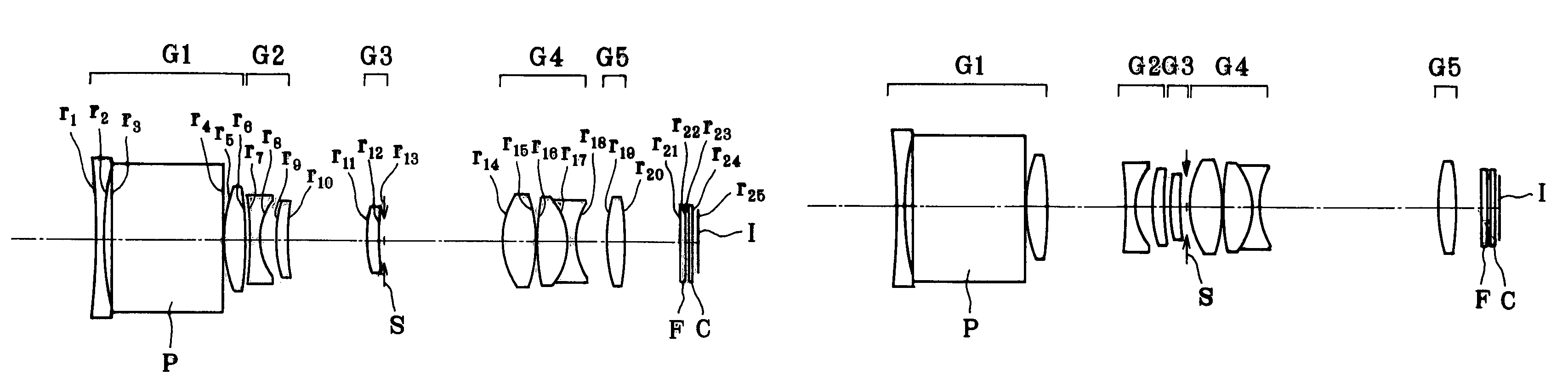
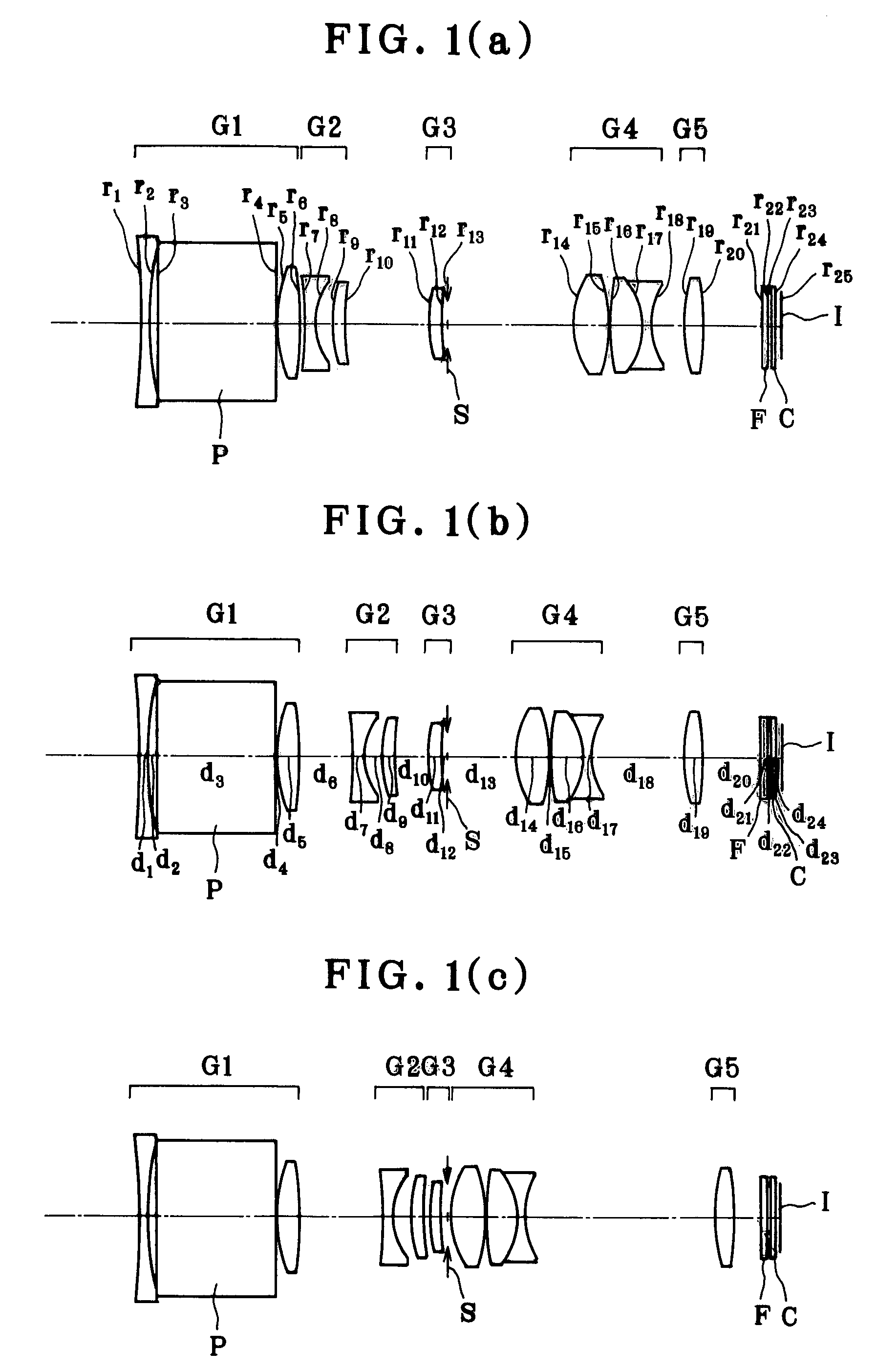
r1 = −130.174d1 = 1.20nd1 = 1.92286νd1 = 20.88r2 = 43.086d2 = 0.94r3 = ∞d3 = 13.80nd2 = 1.80100νd2 = 34.97r4 = ∞d4 = 0.20r5 = 16.322d5 = 2.56nd3 = 1.76802νd3 = 49.24r6 = −47.877d6 = (Variable)(Aspheric)r7 = −35.713d7 = 1.00nd4 = 1.80610νd4 = 40.92r8 = 5.604d8 = 2.17(Aspheric)r9 = 14.804d9 = 1.56nd5 = 1.92286νd5 = 20.88r10 = 41.407d10 = (Variable)r11 = 18.499d11 = 1.39nd6 = 1.92286νd6 = 20.88r12 = 29.001d12 = 0.80r13 = ∞(Stop)d13 = (Variable)r14 = 8.547 (Aspheric)d14 = 4.15nd7 = 1.49700νd7 = 81.54r15 = −13.837d15 = 0.20(Aspheric)r16 = 48.789d16 = 3.81nd8 = 1.61800νd8 = 63.33r17 = −7.488d17 = 0.65nd9 = 1.64769νd9 = 33.79r18 = 7.488d18 = (Variable)r19 = 19.943d19 = 2.32nd10 = 1.52542νd10 = 55.78r20 = −25.502d20 = (Variable)(Aspheric)r21 = ∞d21 = 0.75nd11 = 1.51633νd11 = 64.14r22 = ∞d22 = 0.50r23 = ∞d23 = 0.50nd12 = 1.51633νd12 = 64.14r24 = ∞d24 = 0.37r25 = ∞(Imaging plane)Aspherical Coefficients6th surfaceK = 0.000A4 = 5.53951 × 10⁻⁵A6 = 7.45682 × 10⁻⁸A8 = −9.62928 × 10⁻⁹A10 = 1....

example 2

[0127]

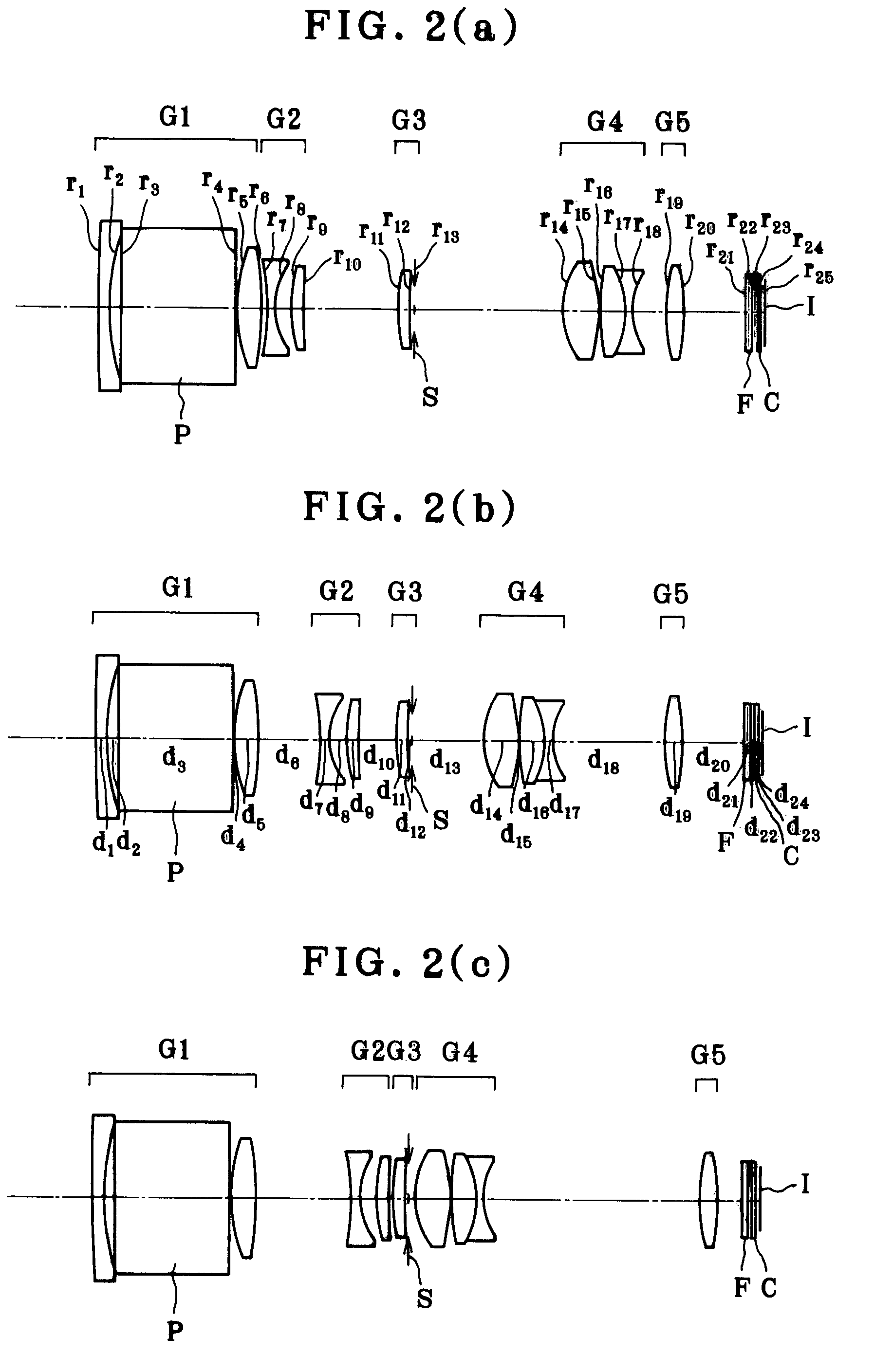
r1 = 252.674d1 = 1.20nd1 = 1.92286νd1 = 20.88r2 = 25.849d2 = 1.55r3 = ∞d3 = 13.80nd2 = 1.80100νd2 = 34.97r4 = ∞d4 = 0.20r5 = 18.961d5 = 2.85nd3 = 1.77377νd3 = 47.17r6 = −36.901d6 = (Variable)(Aspheric)r7 = −24.023d7 = 1.00nd4 = 1.80610νd4 = 40.92r8 = 6.787 (Aspheric)d8 = 1.90r9 = 17.424d9 = 1.45nd5 = 1.92286νd5 = 20.88r10 = 48.482d10 = (Variable)r11 = 21.867d11 = 1.43nd6 = 1.92286νd6 = 20.88r12 = 44.453d12 = 0.62r13 = ∞(Stop)d13 = (Variable)r14 = 8.026 (Aspheric)d14 = 4.33nd7 = 1.49700νd7 = 81.54r15 = −17.674d15 = 0.20(Aspheric)r16 = 32.791d16 = 3.06nd8 = 1.61800νd8 = 63.33r17 = −10.025d17 = 0.70nd9 = 1.64769νd9 = 33.79r18 = 6.700d18 = (Variable)r19 = 19.385d19 = 2.24nd10 = 1.49700νd10 = 81.54r20 = −28.616d20 = (Variable)(Aspheric)r21 = ∞d21 = 0.75nd11 = 1.51633νd11 = 64.14r22 = ∞d22 = 0.50r23 = ∞d23 = 0.50nd12 = 1.51633νd12 = 64.14r24 = ∞d24 = 0.37r25 = ∞(Imaging plane)Aspherical Coefficients6th surfaceK = 0.000A4 = 4.34741 × 10⁻⁵A6 = 1.17640 × 10⁻⁸A8 = −3.40284 × 10⁻⁹A10 = 4...

example 3

[0128]

r1 = −149.275d1 = 1.20nd1 = 1.92286νd1 = 20.88r2 = 27.013d2 = 1.56r3 = ∞d3 = 15.40nd2 = 1.80100νd2 = 34.97r4 = ∞d4 = 0.20r5 = 71.283d5 = 1.87nd3 = 1.69680νd3 = 55.53r6 = −106.683d6 = 0.20r7 = 18.326d7 = 3.41nd4 = 1.69350νd4 = 53.21r8 = −63.160d8 = (Variable)(Aspheric)r9 = −36.828d9 = 0.90nd5 = 1.80610νd5 = 40.92r10 = 7.439 (Aspheric)d10 = 1.21r11 = 25.261d11 = 1.29nd6 = 1.84666νd6 = 23.78r12 = 62.543d12 = (Variable)r13 = 21.357d13 = 2.07nd7 = 1.92286νd7 = 20.88r14 = −49.304d14 = 0.50r15 = ∞(Stop)d15 = 1.12r16 = −20.134d16 = 0.62nd8 = 1.80610νd8 = 40.92r17 = 37.635d17 = (Variable)r18 = 10.943d18 = 4.02nd9 = 1.49700νd9 = 81.54(Aspheric)r19 = −15.182d19 = 0.20(Aspheric)r20 = 25.759d20 = 3.39nd10 = 1.69680νd10 = 55.53r21 = −12.450d21 = 0.70nd11 = 1.80100νd11 = 34.97r22 = 17.026d22 = (Variable)r23 = 262.044d23 = 0.65nd12 = 1.80100νd12 = 34.97r24 = 7.700d24 = 4.33nd13 = 1.58913νd13 = 61.28r25 = −15.657d25 = (Variable)(Aspheric)r26 = ∞d26 = 0.75nd14 = 1.51633νd14 = 64.14r27 = ∞d27 = ...


PUM


Abstract

The invention relates to a bent type zoom optical system comprising a positive first lens group having a reflecting member and remaining fixed upon zooming and a second lens group adapted to move upon zooming, and having a high zoom ratio and a short entire-length, and an imaging apparatus or the like incorporating the same. The zoom optical system comprises the positive first lens group G1 adapted to remain fixed upon zooming and the negative second lens group adapted to move upon zooming. The positive first lens group G1 comprises, in order from the object side, a negative single lens, a reflecting member P and a positive lens unit. The zoom optical system satisfies condition (1) for prevention of fluctuations in the entrance pupil position, condition (2) about the focal length of the first lens group G1, and condition (3) for putting in order the shape of the negative single lens in the first lens group G1.

Description

[0001]This application claims benefit of Japanese Application No. 2006-74044 filed in Japan on Mar. 17, 2006, the contents of which are incorporated by this reference.BACKGROUND OF THE INVENTION[0002]The present invention relates generally to a bent type zoom optical system, and more particularly to a bent type zoom optical system that is reduced in terms of the whole size and thickness albeit including a reflecting surface in its optical path and having a high zoom ratio as well as an imaging apparatus, information processor and electronic camera apparatus incorporating the same.[0003]In recent years, imaging apparatus using an electronic imaging device as in the case of digital still cameras have been widely available. With the development and widespread use of digital still cameras, there are now growing demands for high image quality and size reductions in general, and for slimmer zoom optical systems having a higher zoom ratio in particular.[0004]As one approach to slimmer opti...

Claims


Application Information

Patent Timeline
Patent Type & Authority Patents(United States)
IPC IPC(8): G02B15/14
CPCG02B15/161G02B15/17G02B15/173G02B15/142G02B15/145125G02B15/145129
Inventor NISHIMURA, KAZUYA
Owner OLYMPUS CORP
Why Eureka
Try Eureka