Magnetic head and magnetic disc drive

a magnetic disc drive and magnetic head technology, applied in the direction of magnetic recording, magnetic disk recording, perpendicular magnetisation head, etc., can solve the problems of excessively reducing the magnetic pole surface profile and deteriorating recording characteristics, and achieve excellent recording characteristics, prevent side erase, and increase the skew angle

Inactive Publication Date: 2009-03-24
HITACHI GLOBAL STORAGE TECH NETHERLANDS BV
View PDF6 Cites 41 Cited by
  • Summary
  • Abstract
  • Description
  • Claims
  • Application Information

AI Technical Summary

Benefits of technology

[0007]Embodiments in accordance with the present invention provide a magnetic head and a magnetic disc drive capable of preventing a side erase while providing excellent recording characteristics. According to the particular embodiment of FIG. 5, to prevent the side erase in the increased skew angle state, the first magnetic pole surface 21A is formed in such a shape that the projection area of the first magnetic pole surface 21A follows a track edge 415A positioned on the boundary 43 side in the track 41A in the state where the first magnetic pole surface 21A is positioned on the track 41A at the innermost periphery thereof included in the first region 45A. Likewise, to prevent the side erase in the increased skew angle state, the second magnetic pole surface 21B is formed in such a shape that the projection area of the second magnetic pole surface 21B follows a track edge 413B positioned on the boundary 43 side with respect to a track 41B in the state where the second magnetic pole surface 21B is positioned on the track 41B at the outermost periphery thereof included in the second region 45B.

Problems solved by technology

However, according to the technology, in order to prevent the side erase in the entire tracks included in the recording surface, the profile of the magnetic pole surface is excessively decreased.
As a result, it is impossible to secure the amount of a record magnetic field generated by the magnetic pole surface to a sufficient level, thereby deteriorating recording characteristics.

Method used


Image

  • Magnetic head and magnetic disc drive
  • Magnetic head and magnetic disc drive
  • Magnetic head and magnetic disc drive

Examples


first embodiment

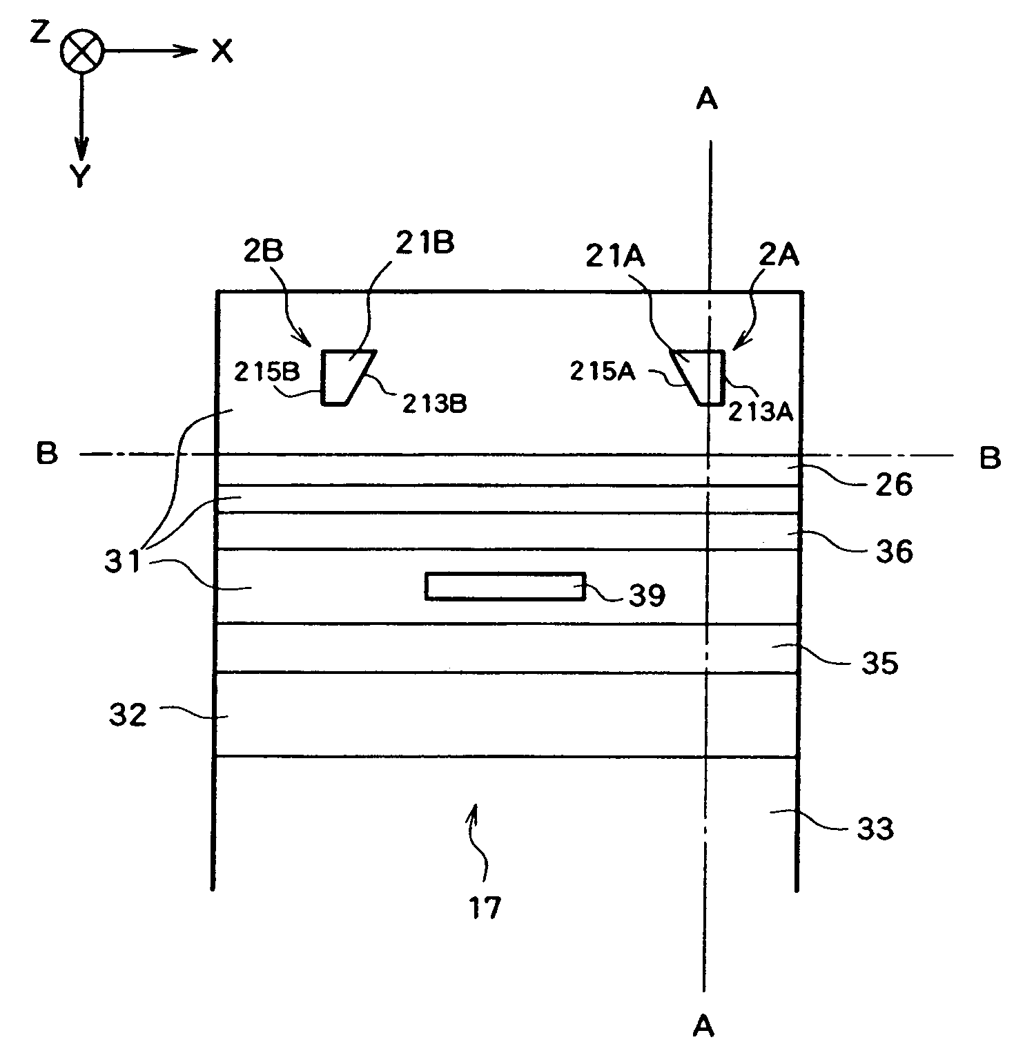
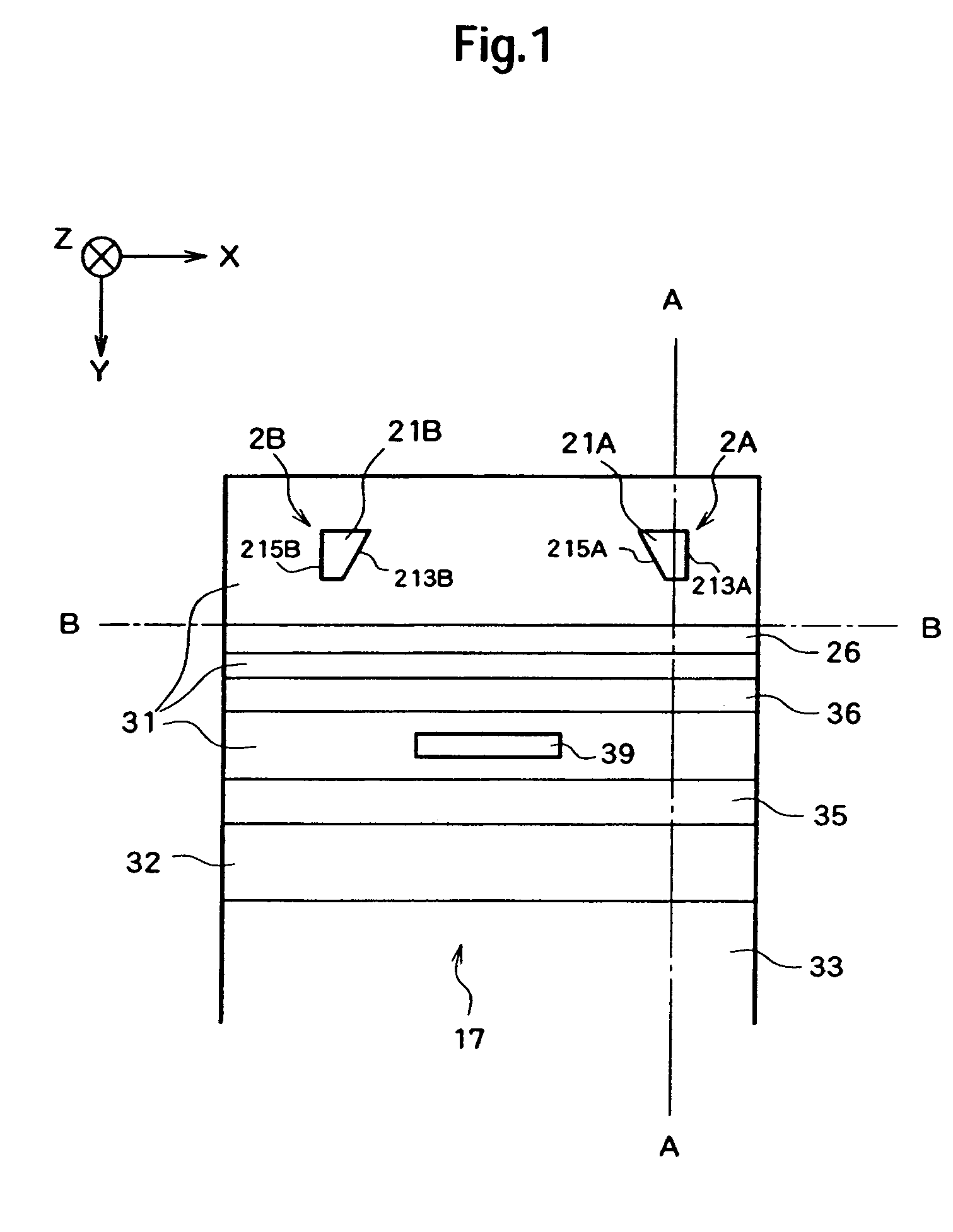
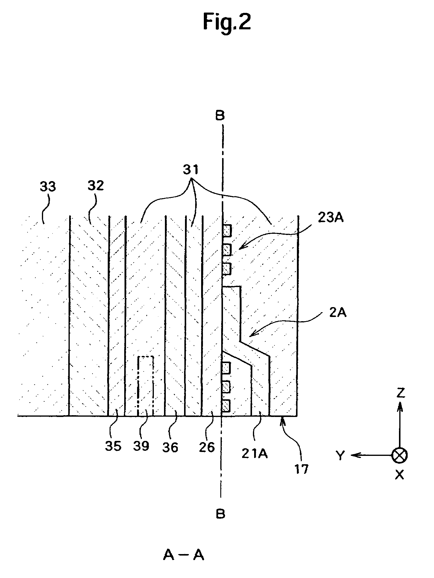
[0033]Hereinafter, a magnetic head will be described. FIG. 1 is a diagram illustrating an air-bearing surface 17 (the surface opposed to a recording surface of a magnetic disc) of a magnetic head 11. FIG. 2 is a sectional view taken along the A-A line in FIG. 1. FIG. 3 is a sectional view taken along the B-B line in FIG. 1. Here, the Y direction is a rotational radius direction when the magnetic head 11 is rotated and the positive direction thereof is a direction toward the rotation axis. The Z direction is a direction perpendicular to the recording surface of the magnetic disc and the positive direction thereof is a direction of the flying movement of the magnetic head 11.

[0034]The magnetic head 11 is configured as a thin film magnetic head adopting a perpendicular magnetic recording system. As shown in FIG. 4, the magnetic head 11 is attached onto the slider 91 and is rotated substantially along the radius direction of the recording surface in the state where the magnetic head 11 ...

second embodiment

[0054]a magnetic head will now be described. FIG. 8 illustrates an air-bearing surface 17 (the surface faces to a recording surface of a magnetic disc) of a magnetic head 12. FIG. 9 is a sectional view taken along the C-C line in FIG. 8.

[0055]In the magnetic head 12, a first write element 2A and a second write element 2B are disposed on layers different from each other (the write elements are arranged in the Y direction). Here, an upper side is defined as a lamination direction in the layer structure, that is, the negative Y direction. On a read shield layer 36, a return pole layer 26A is disposed, and the first write element 2A is provided on the return pole layer 26A. A return pole layer 26B is also disposed thereon with a read shield layer 37 interposed therebetween. The second write element 2B is provided on the return pole layer 26B. The first write element 2A and the second write element 2B in both the X direction and the Y direction may be arbitrarily chosen. Additionally, si...

third embodiment

[0058]a magnetic head will now be described. FIG. 10 is a diagram illustrating an air-bearing surface 17 (which faces to a recording surface of a magnetic disc) of a magnetic head 13.

[0059]In the magnetic head 13, a return pole layer 26 is disposed on the read shield layer 36, and a first write element 2A, a second write element 2B, and a third write element 2C are provided on the same layer which is the return pole layer 26 (the write elements are arranged in the X direction). Here, an upper side is defined as a lamination direction in the layer structure, that is, the negative Y direction. The third write element 2C has the same configuration as the first write element 2A and the second write element 2B. It is possible to change positions of the first write element 2A, the second write element 2B, and the third write element 2C in the X direction. It is also possible to change positions of them in the Y direction.

[0060]FIG. 11 is a diagram illustrating a relationship between a mag...


PUM

PropertyMeasurementUnit
magnetic fieldaaaaaaaaaa
skew angleaaaaaaaaaa
magneticaaaaaaaaaa

Abstract

Embodiments in accordance with present invention provide a magnetic head and a magnetic disc drive capable of preventing a side erase while providing excellent recording characteristics. According to one embodiment, in order to prevent the side erase in an increased skew angle state, a first magnetic pole surface is formed in such a shape that the projection area of the first magnetic pole surface follows a track edge positioned on the boundary side in the track in the state where the first magnetic pole surface is positioned on the track at the innermost periphery thereof included in a first region. Likewise, to prevent the side erase in the increased skew angle state, a second magnetic pole surface is formed in such a shape that the projection area of the second magnetic pole surface follows a track edge positioned on the boundary side with respect to a track in the state where the second magnetic pole surface is positioned on the track at the outermost periphery thereof included in a second region.

Description

CROSS-REFERENCE TO RELATED APPLICATION[0001]The instant nonprovisional patent application claims priority to Japanese Patent Application No. 2006-198770 filed Jul. 20, 2006 and incorporated by reference in its entirety herein for all purposes.BACKGROUND OF THE INVENTION[0002]Recently, in the field of a magnetic disc drives, it is required to further improve a recording density of the magnetic disc. In the conventional in-plane magnetic recording system, magnetization is recorded onto a recording surface of the magnetic disc in a parallel direction. On this account, if a recording interval narrows, a thermal fluctuation effect of recording magnetization cannot be ignored. Accordingly, a perpendicular magnetic recording system has been suggested as a method for enabling a higher recording density. Since the magnetization is recorded onto the recording surface of the magnetic disc in a perpendicular direction according to the perpendicular magnetic recording system, the recording magne...

Claims


Application Information

Patent Timeline
Patent Type & Authority Patents(United States)
IPC IPC(8): G11B20/20G11B5/265
CPCG11B5/012G11B5/1278G11B5/31G11B5/3113G11B5/3116G11B5/5547
Inventor OKAMOTO, HISAOZAITSU, HIDEKI
Owner HITACHI GLOBAL STORAGE TECH NETHERLANDS BV
Why Eureka
Try Eureka