
Method and apparatus for automatically generating a site model

a technology of automatic generation and site model, applied in the field of image processing, can solve the problems of laborious process of extracting information for creating such a database, lack of sufficient information for complete 3d modeling of a building,

Active Publication Date: 2009-03-24
SRI INTERNATIONAL
View PDF20 Cites 176 Cited by
  • Summary
  • Abstract
  • Description
  • Claims
  • Application Information

AI Technical Summary

Benefits of technology

[0009]The disadvantages of the prior art are overcome by a method and apparatus for automatically combining at least one of aerial images and/or oblique images to form a three-dimensional (3D) site model. The apparatus or method is supplied with aerial and/or oblique imagery. The imagery is processed to identify building boundaries and outlines as well as to produce an elevation map. The building boundaries and the elevation map may

Problems solved by technology

Using commercially available software, the process of extracting information for creating such a database is labor-intensive.
Typical aerial photographs lack sufficient information for complete 3D modeling of a building's shape and appearance.
Because the process is so time consuming, the process is generally used for only a select number of buildings.

Method used


Image

  • Method and apparatus for automatically generating a site model
  • Method and apparatus for automatically generating a site model
  • Method and apparatus for automatically generating a site model

Examples


Embodiment Construction

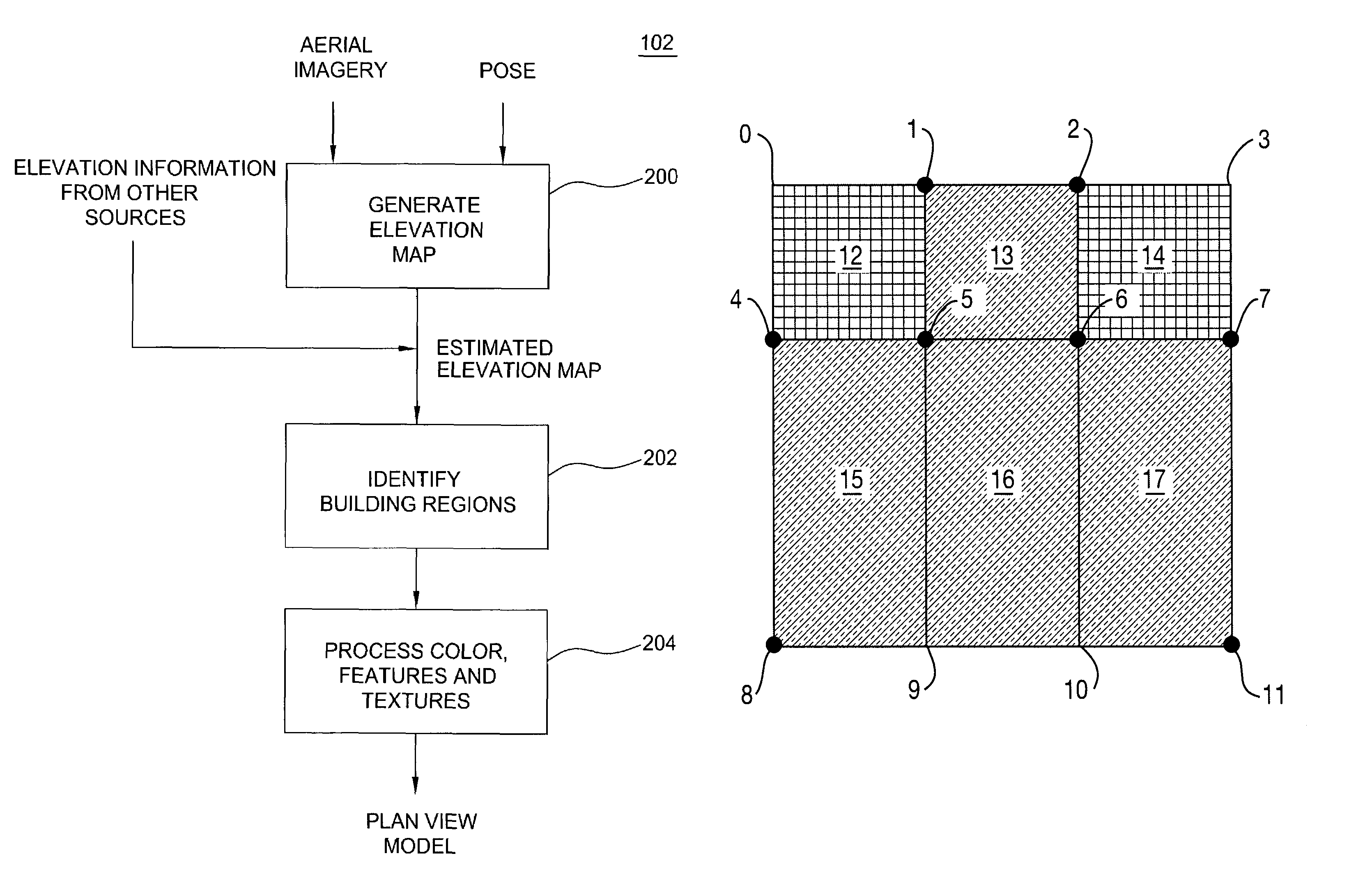
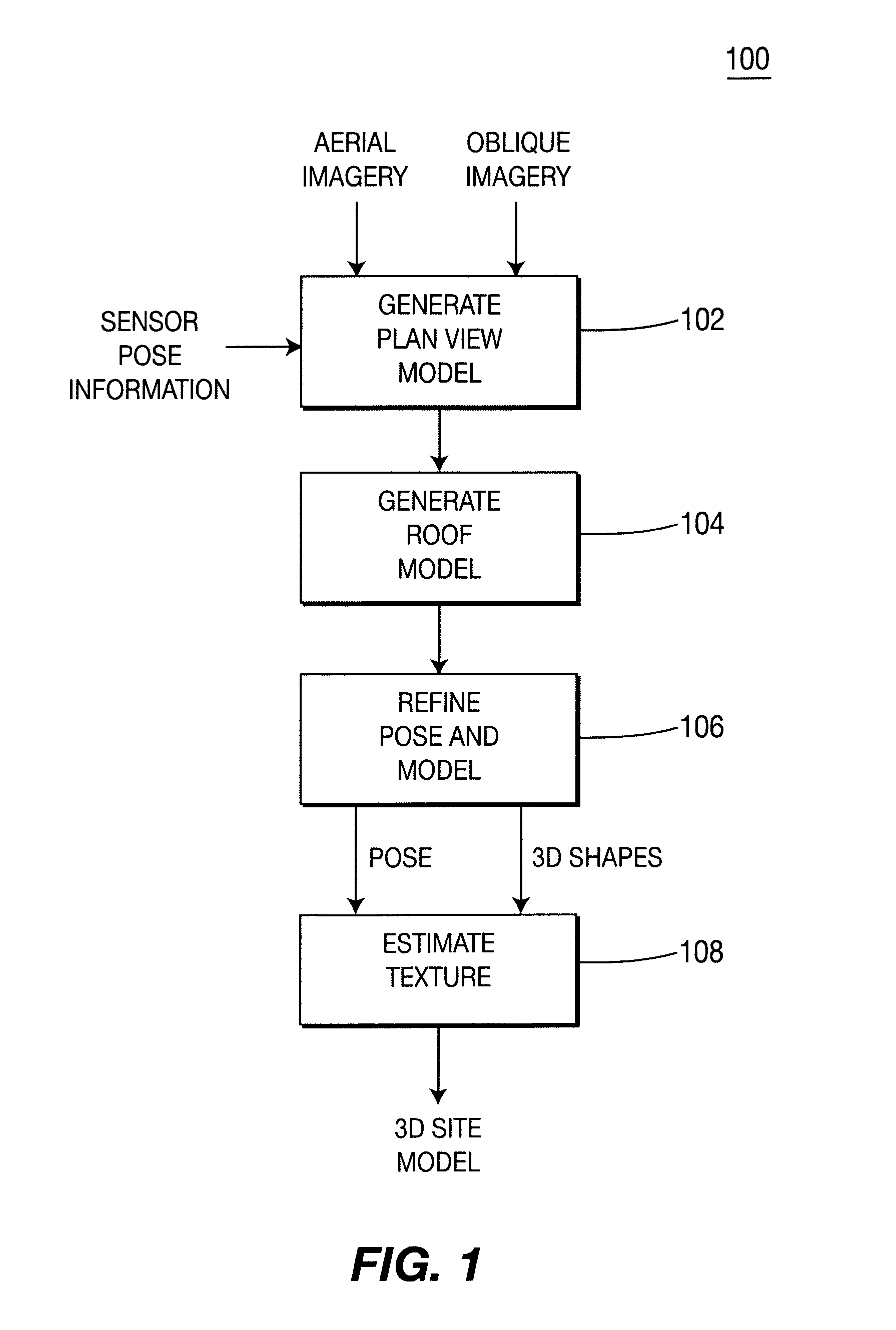
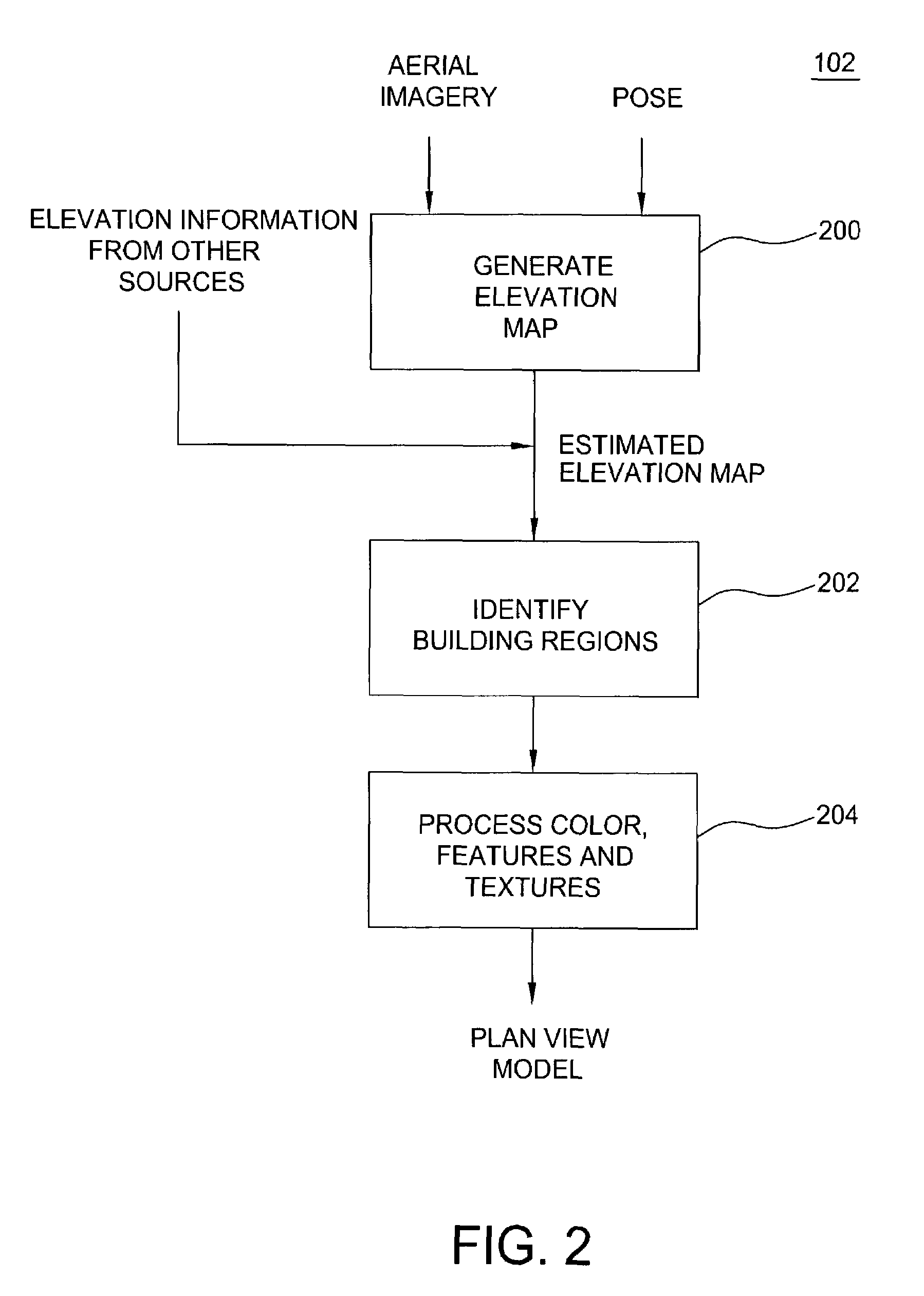
[0021]FIG. 1 depicts a high-level flow diagram of one embodiment of a method 100 of the present invention. The method 100 is supplied with at least one of aerial imagery and oblique imagery of a scene as well as pose information regarding the sensors used to produce both the aerial and oblique imagery. The aerial imagery is produced from above the scene in a substantially vertical orientation, e.g., an aerial video image taken from an airplane. The aerial imagery is generally acquired using large format, film-based still photography, digital scanners or one or more video cameras. Alternatively, the imagery can be produced by creating a mosaic comprising a plurality of small format photographs or video frames.

[0022]The oblique imagery is generated by a film or digital still camera(s) or at least one video camera. However, to produce high quality textured 3D models, the oblique imagery is generally video captured from a continuously moving platform that provides gap-free coverage and ...


PUM


Abstract

A method and apparatus for automatically combining aerial images and oblique images to form a three-dimensional (3D) site model. The apparatus or method is supplied with aerial and oblique imagery. The imagery is processed to identify building boundaries and outlines as well as to produce a depth map. The building boundaries and the depth map may be combined to form a 3D plan view model or used separately as a 2D plan view model. The imagery and plan view model is further processed to determine roof models for the buildings in the scene. The result is a 3D site model having buildings represented rectangular boxes with accurately defined roof shapes.

Description

CROSS-REFERENCE TO RELATED APPLICATIONS[0001]This application claims benefit of U.S. provisional patent application Ser. No. 60 / 303,492, filed Jul. 6, 2001, which is herein incorporated by reference.GOVERNMENT RIGHTS IN THIS INVENTION[0002]This invention was made with U.S. government support under U.S. Navy Contract Number N0001999C1385. The U.S. government may have certain rights in this invention.BACKGROUND OF THE INVENTION[0003]1. Field of the Invention[0004]The invention relates to image processing and, more particularly, relates to techniques for automatically generating a site model from images of a site.[0005]2. Description of the Related Art[0006]The mainstay of geographical information systems is the depiction of land occupied by buildings using a two-dimensional map. Increasingly, there is a need for three-dimensional (3D) representations of buildings to augment the geographical information. Such 3D information may be required in architectural design application and wirele...

Claims


Application Information

Patent Timeline
IPC IPC(8): G06F17/10G06F17/50G06K9/00G06T15/00G06T15/10G06T15/50G06T17/00G06T17/05G06T17/10
CPCG06F17/5004G06K9/00597G06T17/05G06T17/10G06T2200/08G06F30/13G06V40/18
Inventor GUO, YANLINKUMAR, RAKESHHSU, STEPHEN CHARLESSAWHNEY, HARPREET SINGH
Owner SRI INTERNATIONAL
Learn More