Method and apparatus for placing assist features by identifying locations of constructive and destructive interference

a technology of constructive and destructive interference and placement rules, which is applied in the direction of photomechanical treatment, instruments, and total factory control, etc., can solve the problems of difficult creation and maintenance of a robust set of placement rules that are guaranteed to work properly for arbitrary configurations, and high cost of maintaining rules in a manufacturing environmen

Active Publication Date: 2009-03-24
SYNOPSYS INC
View PDF6 Cites 222 Cited by
  • Summary
  • Abstract
  • Description
  • Claims
  • Application Information

AI Technical Summary

Problems solved by technology

Unfortunately, optical behavior with off-axis illumination is complex and requires an elaborate set of assist feature synthesis rules.
As a result, creating and maintaining a robust set of placement rules that are guaranteed to work properly for arbitrary configurations is very difficult.
In addition, maintaining rules in a manufacturing environment is very expensive.

Method used


Image

  • Method and apparatus for placing assist features by identifying locations of constructive and destructive interference
  • Method and apparatus for placing assist features by identifying locations of constructive and destructive interference
  • Method and apparatus for placing assist features by identifying locations of constructive and destructive interference

Examples


Embodiment Construction

Integrated Circuit Design and Fabrication

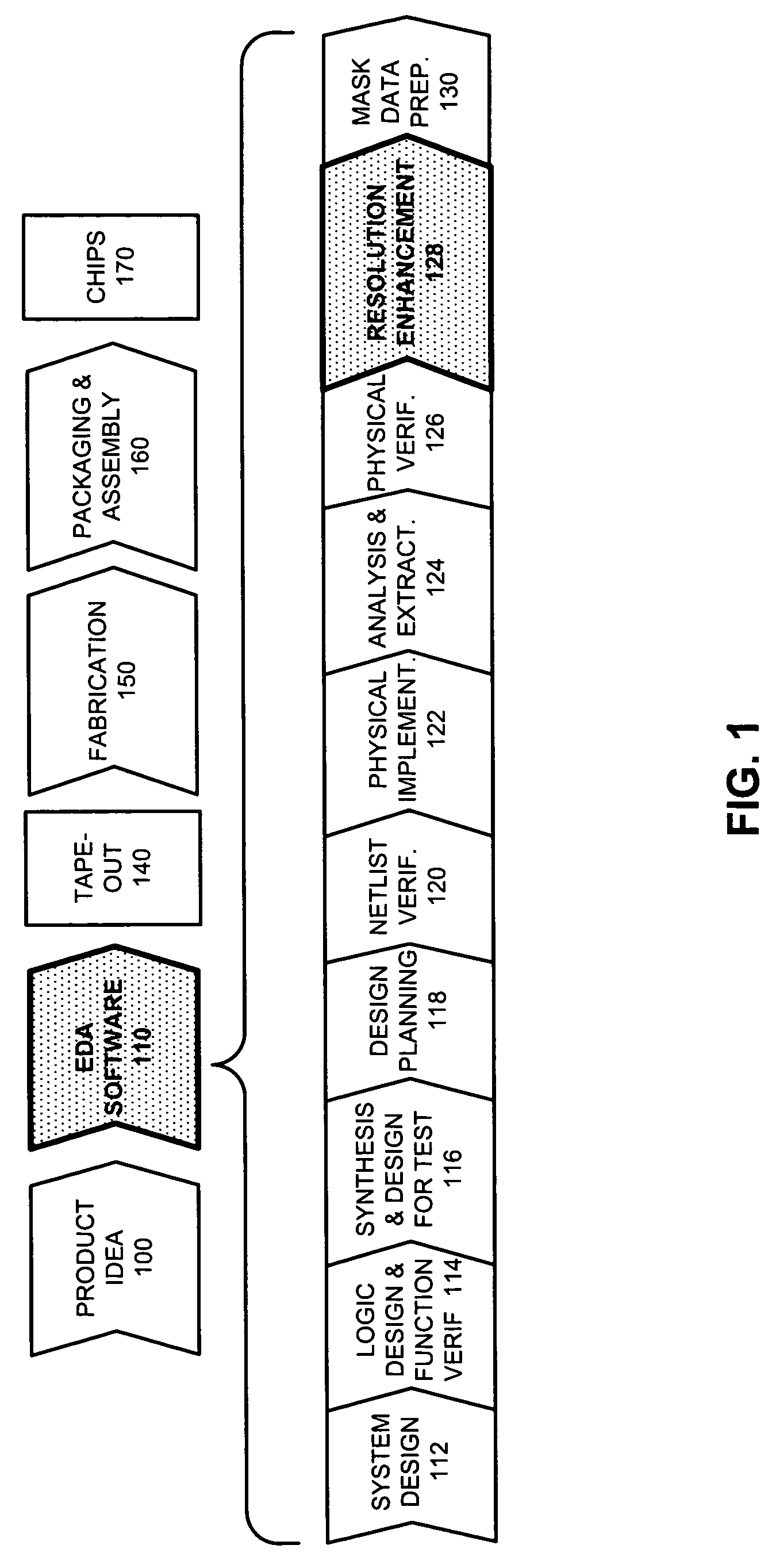
[0026]FIG. 1 illustrates various steps in the design and fabrication of an integrated circuit in accordance with an embodiment of the present invention. The process starts with a product idea (step 100). Next, the product idea is realized using an integrated circuit, which is designed using Electronic Design Automation (EDA) software (step 110). Once the circuit design is finalized, it is taped-out (step 140). After tape-out, the process goes through fabrication (step 150), packaging, and assembly (step 160). The process eventually culminates with the production of chips (step 170).

[0027]The EDA software design step 110, in turn, includes a number of sub-steps, namely, system design (step 112), logic design and function verification (step 114), synthesis and design for test (step 116), design planning (step 118), netlist verification (step 120), physical implementation (step 122), analysis and extraction (step 124), physical verification (ste...


PUM


Abstract

One embodiment of the present invention provides a system that determines a location in a layout to place an assist feature. During operation, the system receives a layout of an integrated circuit. Next, the system selects an evaluation point in the layout. The system then chooses a candidate location in the layout for placing an assist feature. Next, the system determines the final location in the layout to place an assist feature by, iteratively, (a) selecting perturbation locations for placing representative assist features in the proximity of the candidate location, (b) computing aerial-images using an image intensity model, the layout, and by placing representative assist features at the candidate location and the perturbation locations, (c) calculating image-gradient magnitudes at the evaluation point based on the aerial-images, and (d) updating the candidate location for the assist feature based on the image-gradient magnitudes.

Description

BACKGROUND[0001]1. Field of the Invention[0002]The present invention is related to integrated circuit fabrication. More specifically, the present invention is related to a method and apparatus for placing assist features in a mask layout using an aerial-image intensity model.[0003]2. Related Art[0004]The dramatic improvements in semiconductor integration densities in recent years have largely been achieved through corresponding improvements in semiconductor manufacturing technologies.[0005]One such semiconductor manufacturing technology involves placing assist features on a mask layout. Note that assist features can be printing (e.g., super-resolution assist features) or non-printing (e.g., sub-resolution assist features). In either case, these assist features are meant to improve the lithographic performance of the lines intended to be printed on the wafer.[0006]Present techniques for placing assist features use a rule-based methodology in which assist features are placed based on ...

Claims


Application Information

Patent Timeline
Patent Type & Authority Patents(United States)
IPC IPC(8): G06F17/50
CPCG03F1/144G03F1/36G06F17/5068G06F2217/12G06F30/39G06F2119/18Y02P90/02
Inventor MELVIN, III, LAWRENCE S.
Owner SYNOPSYS INC
Why Eureka
Try Eureka