Amplified spontaneous emission reflector-based gain-clamped fiber amplifier
a fiber amplifier and reflector technology, applied in the field of fiber amplifiers, can solve the problems of amplification of conventional optical amplifiers, inability to meet the needs of customers, and temporarily fluctuating intensity of optical signals, so as to achieve a wide dynamic range and reduce noise figure factors
- Summary
- Abstract
- Description
- Claims
- Application Information
AI Technical Summary
Benefits of technology
Problems solved by technology
Method used
Image
Examples
first embodiment
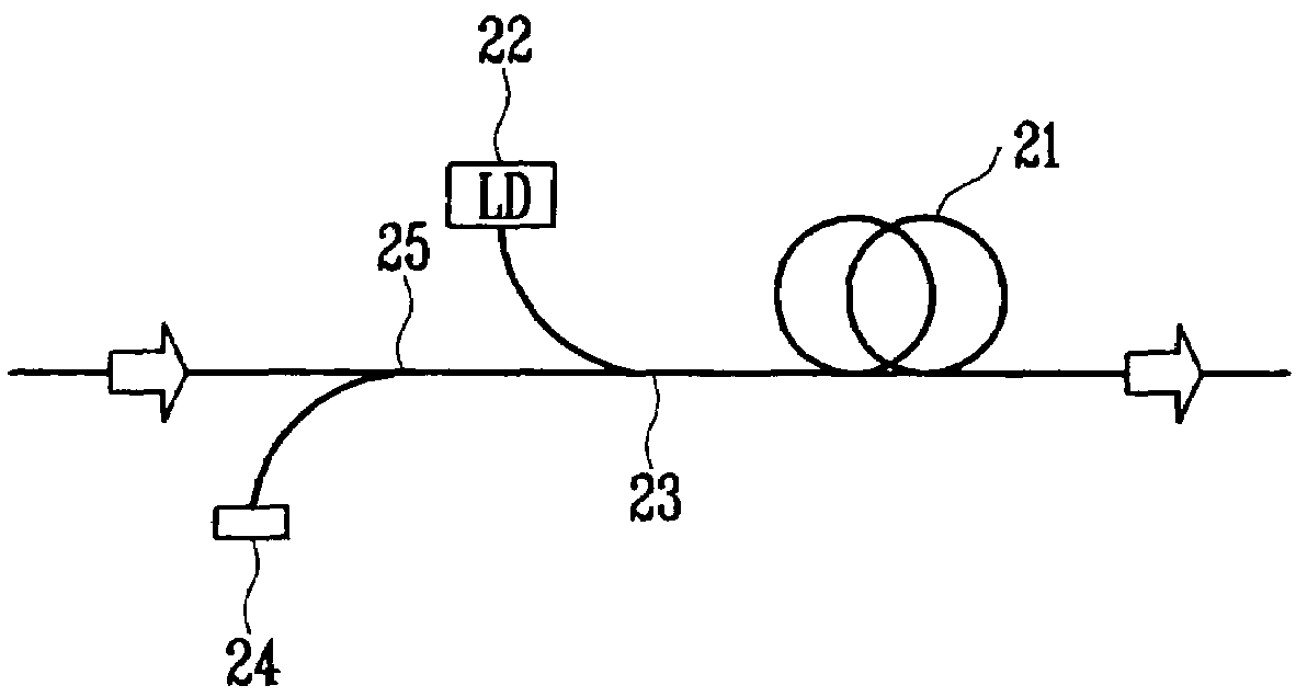
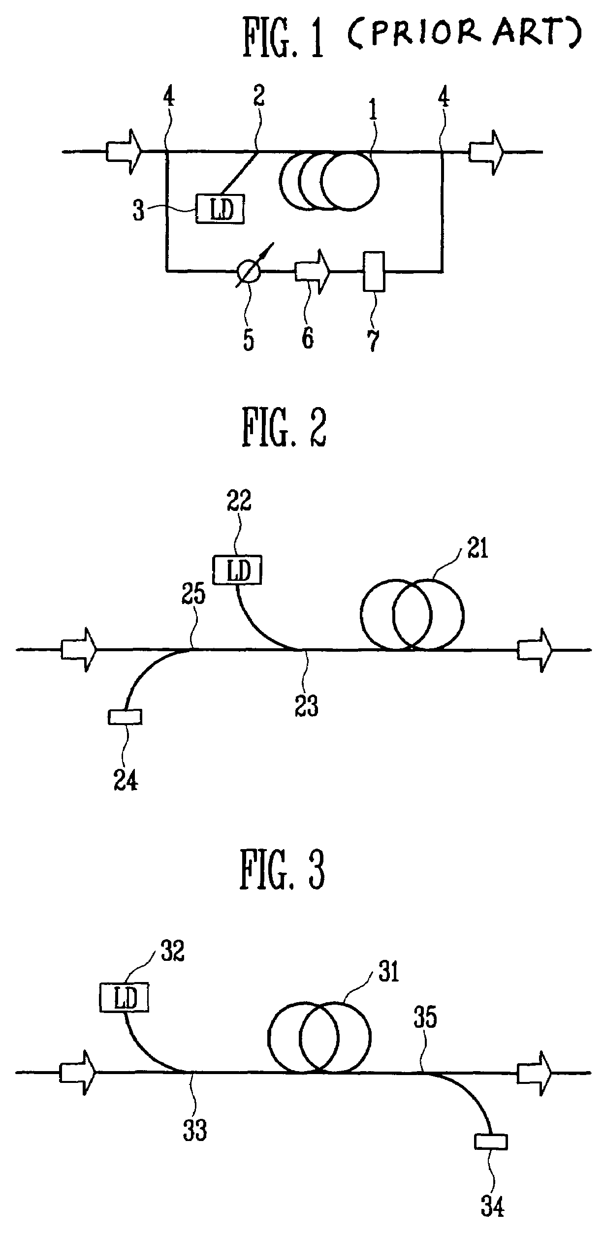
[0029]FIG. 2 is a schematic diagram of an amplified spontaneous emission (ASE) reflector-based gain-clamped fiber amplifier according to the present invention.
[0030]As a gain medium 21 for amplifying an optical signal, for example, an Erbium-doped fiber (EDF) is used. A laser diode (LD) 22 provides pump light having a center wavelength of, for example, 980nm, for population inversion of the gain medium 21, and a wavelength division multiplexing (WDM) coupler 23 couples the pump light provided from the laser diode (LD) 22 to the gain medium 21. In addition, a transmission and isolation unit 25 is arranged at an input stage to periodically transmit the optical signal provided from the outside to send to the gain medium 21 through the WDM coupler 23 and send ASE having a different wavelength from the optical signal coming back from the gain medium 21 to a reflection mirror 24.
[0031]When the pump light provided from the laser diode (LD) 22 is incident on the gain medium 21 through the W...
second embodiment
[0032]FIG. 3 is a schematic diagram of an amplified spontaneous emission (ASE) reflector-based gain-clamped fiber amplifier according to the present invention;
[0033]As a gain medium 31 for amplifying an optical signal, for example, an Erbium-doped fiber (EDF) is used. A laser diode (LD) 32 provides pump light having a center wavelength of, for example, 980 nm, for population inversion of the gain medium 31, and a wavelength division multiplexing (WDM) coupler 33 couples the pump light provided from the laser diode (LD) 32 to the gain medium 31. In addition, a transmission and isolation unit 35 is arranged at an output stage to periodically transmit the optical signal amplified from the gain medium 31 to output to the outside and send ASE having a different wavelength from the optical signal from the gain medium 31 to a reflection mirror 34.
[0034]When the pump light provided from the laser diode (LD) 32 is incident on the gain medium 31 through the WDM coupler 33, each atomic energy ...
third embodiment
[0048]FIG. 7 is a schematic diagram of an ASE reflector-based gain-clamped fiber amplifier according to the present invention, in which an amplifier for amplifying the ASE is further included to increase a dynamic range.
[0049]As a gain medium 71 for amplifying an optical signal, for example, an Erbium-doped fiber (EDF) is used. A laser diode (LD) 72 provides pump light having a center wavelength of, for example, 980nm, for population inversion of the gain medium 71, and a wavelength division multiplexing (WDM) coupler 73 couples the pump light provided from the laser diode (LD) 72 to the gain medium 71. In addition, a transmission and isolation units 75 is arranged at an input stage to periodically transmit the optical signal provided from the outside to send to the gain medium 71 through the WDM coupler 73 and send ASE having a different wavelength from the optical signal coming back from the gain medium 71 to a reflection mirror 74. An optical amplifier 76 is arranged between the ...
PUM
 Abstract
Description
Claims
Application Information
 - R&D
- Intellectual Property
- Life Sciences
- Materials
- Tech Scout
- Unparalleled Data Quality
- Higher Quality Content
- 60% Fewer Hallucinations
Browse by: Latest US Patents, China's latest patents, Technical Efficacy Thesaurus, Application Domain, Technology Topic, Popular Technical Reports.
© 2025 PatSnap. All rights reserved.Legal|Privacy policy|Modern Slavery Act Transparency Statement|Sitemap|About US| Contact US: help@patsnap.com


